SIK Experiment Guide for the Arduino 101/Genuino 101 Board
 D___Run___
 Experiment 2: Reading a Potentiometer
Introduction
In this circuit you will work with a potentiometer. You will learn how to use a potentiometer to control the timing of a blinking LED by reading a sensor and storing it as a variable, then using it as your delay timing.
Parts Needed
You will need the following parts:
- 1x Breadboard
- 1x Arduino 101 or Genuino 101 board
- 1x LED
- 1x 100Ω Resistor
- 7x Jumper Wires
- 1x Potentiometer
Didn't Get the SIK?
If you are conducting this experiment and didn't get the SIK, we suggest using these parts:


You will also need either an Arduino 101 OR Genuino 101 board.


Suggested Reading
Before continuing with this experiment, we recommend you be familiar with the concepts in the following tutorial:
Introducing the Potentiometer
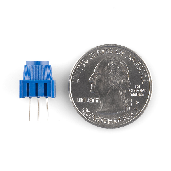
A potentiometer is a resistance-based analog sensor that changes its internal resistance based on the rotation of its knob. The potentiometer has an internal voltage divider enabling you to read the change in voltage on the center pin with a microcontroller (the 101 board). To hook up the potentiometer, attach the two outside pins to a supply voltage (3.3V in this circuit) and ground. It doesn’t matter which is connected where, as long as one is connected to power, and the other to ground. The center pin is then connected to an analog input pin so the 101 can measure the change in voltage. When you twist the knob, the sensor reading will change!
**Note: The potentiometer included in the kit has three marks on it that will help you figure out which breadboard rows the pins are plugged into. **
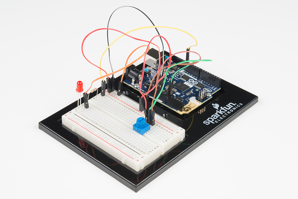
Hardware Hookup
Ready to start hooking everything up? Check out the wiring diagram and hookup table below to see how everything is connected.
| Polarized Components | Pay special attention to the component’s markings indicating how to place it on the breadboard. Polarized components can only be connected to a circuit in one direction. Polarized components are highlighted with a yellow warning triangle in the table. |
Wiring Diagram for the Experiment

Open the Sketch
Open the Arduino IDE software on your computer. Coding in the Arduino language will control your circuit. Open the code for Circuit 2 by accessing the “101 SIK Guide Code” you downloaded and placed into your “Examples” folder earlier.
To open the code go to: File > Examples > 101 SIK Guide Code > Circuit_02
**Copy and paste the following code into the Arduino IDE. Hit upload, and see what happens! **
language:cpp
/* SparkFun Inventor's Kit
Example sketch 02

POTENTIOMETER

  Measure the position of a potentiometer and use it to
  control the blink rate of an LED. Turn the knob to make
  it blink faster or slower!

This sketch was written by SparkFun Electronics,
with lots of help from the Arduino community.
This code is completely free for any use.
Visit http://learn.sparkfun.com/products/2 for SIK information.
Visit http://www.arduino.cc to learn about Arduino.
*/


//Create global variables (variables that can be used anywhere in our sketch)

// Here we're creating a variable called "sensorPin" of type "int"
// and initializing it to have the value "0," which is the analog input pin the pot is     //conected to.
int sensorPin = 0;

// Variable for storing the pin number that the LED is connected to
int ledPin = 13;

// this function runs once when the sketch starts up
void setup()
{
  //set ledPin (13) as an OUTPUT
  pinMode(ledPin, OUTPUT);
}

// this function runs repeatedly after setup() finishes
void loop()
{

  //create a local variable (variable that can only be used inside of loop() to store       //a sensor value called sensorValue
  int sensorValue;

  //use the analogRead() function to read sensorPin and store the value in sensorValue
  sensorValue = analogRead(sensorPin);

  // Turn the LED on
  digitalWrite(ledPin, HIGH);


  delay(sensorValue);

  // Turn the LED off
  digitalWrite(ledPin, LOW);

 //delay for the value of sensorValue
  delay(sensorValue);

  //loop back to the top
}
Code to Note
int sensorValue;
A “variable” is a placeholder for values that may change in your code. You must introduce, or "declare," variables before you use them; here you are declaring a variable called sensorValue, of type "int" (integer). Don't forget that variable names are case sensitive!
sensorValue = analogRead(sensorPin);
Use the analogRead() function to read the value on an analog pin. analogRead() takes one parameter, the analog pin you want to use ("sensorPin"), and returns a number ("sensorValue") between 0 (0 volts) and 1023 (3.3 volts).
delay(sensorValue);
Microcontrollers are very fast, capable of running thousands of lines of code each second. To slow it down so that we can see what it's doing, we'll often insert delays into the code. delay() counts in milliseconds; there are 1000 ms in one second.
What You Should See
You should see the LED blink faster or slower in accordance with your potentiometer. If it isn't working, make sure you have assembled the circuit correctly and verified and uploaded the code to your board, or see the Troubleshooting section.
Troubleshooting
Sporadically Working
This is most likely due to a slightly dodgy connection with the potentiometer's pins. This can usually be conquered by holding the potentiometer down or moving the potentiometer circuit somewhere else on your breadboard.
Not Working
Make sure you haven’t accidentally connected the wiper (center pin), the resistive element in the potentiometer, to digital pin 0 rather than analog pin 0 (the row of pins beneath the power pins).
LED Not Lighting Up
LEDs will only work in one direction. Double check your connections.