SIK Experiment Guide for the Arduino 101/Genuino 101 Board (French)
This Tutorial is Retired!
This tutorial covers concepts or technologies that are no longer current. It's still here for you to read and enjoy, but may not be as useful as our newest tutorials.
 D___Run___
 Expérience 16 : Utilisez un registre à décalage
Introduction
Nous allons maintenant plonger dans le monde des CI (circuits intégrés). Dans cette expérience, vous allez apprendre à utiliser un registre à décalage. Ce composant fournira à votre carte 101 huit sorties supplémentaires en n'utilisant que trois broches de la carte. Pour cette expérience, vous vous entraînerez à utiliser le registre à décalage pour contrôler huit LED. Exact, deux LED de plus qu'à l'expérience 4 !
Composants nécessaires
Vous aurez besoin des composants suivants :
- 1 plaque Breadboard
- 1 carte Arduino 101 ou Genuino 101
- 8 LED
- 8 résistances 330 Ω
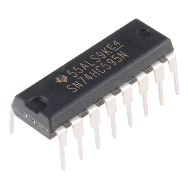
- 1 registre à décalage 8 bits - 74HC595
- 19 cavaliers
Vous n'avez pas le SIK ?
Pour réaliser cette expérience sans le SIK, nous vous suggérons d'utiliser les composants suivants :


Vous aurez également besoin d'une carte Arduino 101 ou Genuino 101.


Lectures suggérées
Avant de poursuivre cette expérience, nous vous recommandons de vous familiariser avec les concepts des tutoriels suivants :
Présentation du registre à décalage
Le registre à décalage est un circuit intégré (CI). Les CI sont de minuscules boîtiers en plastique hermétique contenant des circuits couramment employés. Ils agissent comme des composants individuels pour effectuer une tâche spécifique et simplifier le processus, long et encombrant, de conception de circuits.
Le registre à décalage vous permet de contrôler jusqu'à huit sorties en n'utilisant que trois broches sur votre carte 101. Vous contrôlez ainsi davantage de sorties avec moins de broches qu'à l'expérience 4, qui a nécessité six broches pour six sorties individuelles.
Comparons les données qui pénètrent dans le registre à décalage à un train composé de huit wagons. Si un wagon est rempli de marchandises, les données le représentent avec un 1. S'il est vide, les données le représentent avec un 0. Lorsque tout le train est entré dans le registre à décalage, il est décomposé et chaque wagon est placé sur ses propres rails. Ces rails peuvent être comparés aux huit broches de sortie du registre à décalage. Si le wagon est plein (1), la broche à laquelle il est connecté est à l'état HIGH. S'il est vide (0), l'état de la broche est LOW. Si vous envoyez constamment des trains dans le registre à décalage, vous pouvez animer des LED ou contrôler un appareil tel qu'un afficheur 7 segments pour un compte à rebours ou même de nombreux moteurs qui tournent à des moments différents. Tout cela se produit en envoyant simplement au registre à décalage des trains avec différentes structures de 1 et de 0.
Pour en savoir plus sur les trains registres à décalage, consultez notre Tutoriel sur les registres à décalage.
Branchement du matériel
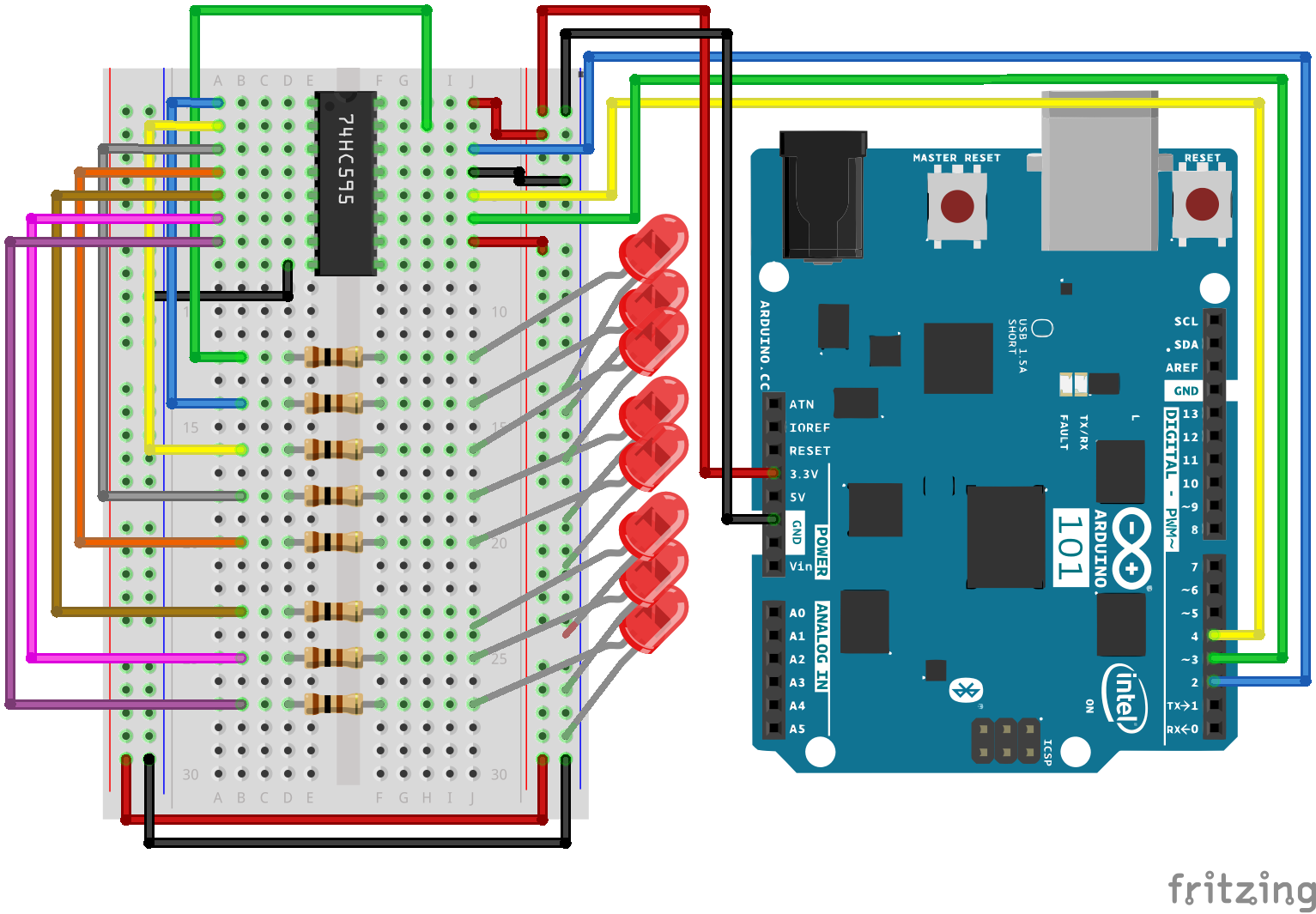
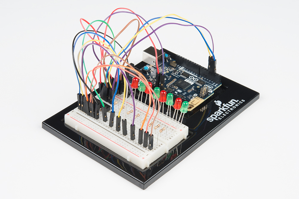
Vous êtes prêt à tout raccorder ? Consultez le schéma de câblage ci-dessous pour savoir comment faire.
| Composants polarisés | Faites particulièrement attention aux marquages indiquant comment placer les composants sur la plaque breadboard, car les composants polarisés ne peuvent être connectés à un circuit que dans une direction. |
Schéma de câblage de l'expérience
Ouverture du sketch
Ouvrez l'EDI Arduino sur votre ordinateur. Le codage en langage Arduino contrôlera votre circuit. Ouvrez le code du Circuit 16 en accédant au « Code du guide SIK 100 » que vous avez précédemment téléchargé et placé dans votre dossier « Examples ».
Pour ouvrir le code, cliquez sur : File > Examples >101 SIK Guide Code > Circuit_16
Vous pouvez également copier et coller le code suivant dans l'EDI Arduino. Cliquez sur Télécharger et observez ce qu'il se passe.
language:cpp
/*
SparkFun Inventor's Kit
Example sketch 16

SHIFT REGISTER

  Use a shift register to turn three pins into eight (or more!)
  outputs

This sketch was written by SparkFun Electronics,
with lots of help from the Arduino community.
This code is completely free for any use.
Visit http://learn.sparkfun.com/products/2 for SIK information.
Visit http://www.arduino.cc to learn more about Arduino.
*/

// Pin definitions:
// The 74HC595 uses a type of serial connection called SPI
// (Serial Peripheral Interface) that requires three pins:

int datapin = 2;
int clockpin = 3;
int latchpin = 4;

// We'll also declare a global variable for the data we're
// sending to the shift register:

byte data = 0;

void setup()
{
  // Set the three SPI pins to be outputs:

  pinMode(datapin, OUTPUT);
  pinMode(clockpin, OUTPUT);
  pinMode(latchpin, OUTPUT);
}

void loop()
{
  // We're going to use the same functions we played with back
  // in circuit 04, "Multiple LEDs," we've just replaced
  // digitalWrite() with a new function called shiftWrite()
  // (see below). We also have a new function that demonstrates
  // binary counting.

  // To try the different functions below, uncomment the one
  // you want to run, and comment out the remaining ones to
  // disable them from running.

  oneAfterAnother();      // All on, all off

  //oneOnAtATime();       // Scroll down the line

  //pingPong();           // Like above, but back and forth

  //randomLED();          // Blink random LEDs

  //marquee();

  //binaryCount();        // Bit patterns from 0 to 255
}

void shiftWrite(int desiredPin, boolean desiredState)

// This function lets you make the shift register outputs
// HIGH or LOW in exactly the same way that you use digitalWrite().

// Like digitalWrite(), this function takes two parameters:

//    "desiredPin" is the shift register output pin
//    you want to affect (0-7)

//    "desiredState" is whether you want that output
//    to be HIGH or LOW

// Inside the Arduino, numbers are stored as arrays of "bits,"
// each of which is a single 1 or 0 value. Because a "byte" type
// is also eight bits, we'll use a byte (which we named "data"
// at the top of this sketch) to send data to the shift register.
// If a bit in the byte is "1," the output will be HIGH. If the bit
// is "0," the output will be LOW.

// To turn the individual bits in "data" on and off, we'll use
// a new Arduino commands called bitWrite(), which can make
// individual bits in a number 1 or 0.
{
  // First we'll alter the global variable "data," changing the
  // desired bit to 1 or 0:

  bitWrite(data,desiredPin,desiredState);

  // Now we'll actually send that data to the shift register.
  // The shiftOut() function does all the hard work of
  // manipulating the data and clock pins to move the data
  // into the shift register:

  shiftOut(datapin, clockpin, MSBFIRST, data);

  // Once the data is in the shift register, we still need to
  // make it appear at the outputs. We'll toggle the state of
  // the latchPin, which will signal the shift register to "latch"
  // the data to the outputs. (Latch activates on the high-to
  // -low transition).

  digitalWrite(latchpin, HIGH);
  digitalWrite(latchpin, LOW);
}

/*
oneAfterAnother()

This function will light one LED, delay for delayTime, then light
the next LED, and repeat until all the LEDs are on. It will then
turn them off in the reverse order.
*/

void oneAfterAnother()
{
  int index;
  int delayTime = 100; // Time (milliseconds) to pause between LEDs
                       // Make this smaller for faster switching

  // Turn all the LEDs on:

  // This for() loop will step index from 0 to 7
  // (putting "++" after a variable means add one to it)
  // and will then use digitalWrite() to turn that LED on.

  for(index = 0; index <= 7; index++)
  {
    shiftWrite(index, HIGH);
    delay(delayTime);
  }

  // Turn all the LEDs off:

  // This for() loop will step index from 7 to 0
  // (putting "--" after a variable means subtract one from it)
  // and will then use digitalWrite() to turn that LED off.

  for(index = 7; index >= 0; index--)
  {
    shiftWrite(index, LOW);
    delay(delayTime);
  }
}

/*
oneOnAtATime()

This function will step through the LEDs, lighting one at at time.
*/

void oneOnAtATime()
{
  int index;
  int delayTime = 100; // Time (milliseconds) to pause between LEDs
                       // Make this smaller for faster switching

  // step through the LEDs, from 0 to 7

  for(index = 0; index <= 7; index++)
  {
    shiftWrite(index, HIGH);    // turn LED on
    delay(delayTime);       // pause to slow down the sequence
    shiftWrite(index, LOW); // turn LED off
  }
}

/*
pingPong()

This function will step through the LEDs, lighting one at at time,
in both directions.
*/

void pingPong()
{
  int index;
  int delayTime = 100; // time (milliseconds) to pause between LEDs
                       // make this smaller for faster switching

  // step through the LEDs, from 0 to 7

  for(index = 0; index <= 7; index++)
  {
    shiftWrite(index, HIGH);    // turn LED on
    delay(delayTime);       // pause to slow down the sequence
    shiftWrite(index, LOW); // turn LED off
  }

  // step through the LEDs, from 7 to 0

  for(index = 7; index >= 0; index--)
  {
    shiftWrite(index, HIGH);    // turn LED on
    delay(delayTime);       // pause to slow down the sequence
    shiftWrite(index, LOW); // turn LED off
  }
}

/*
randomLED()

This function will turn on random LEDs. Can you modify it so it
also lights them for random times?
*/

void randomLED()
{
  int index;
  int delayTime = 100; // time (milliseconds) to pause between LEDs
                       // make this smaller for faster switching

  // The random() function will return a semi-random number each
  // time it is called. See http://arduino.cc/en/Reference/Random
  // for tips on how to make random() more random.

  index = random(8);    // pick a random number between 0 and 7

  shiftWrite(index, HIGH);  // turn LED on
  delay(delayTime);     // pause to slow down the sequence
  shiftWrite(index, LOW);   // turn LED off
}

/*
marquee()

This function will mimic "chase lights" like those around signs.
*/

void marquee()
{
  int index;
  int delayTime = 200; // Time (milliseconds) to pause between LEDs
                       // Make this smaller for faster switching

  // Step through the first four LEDs
  // (We'll light up one in the lower 4 and one in the upper 4)

  for(index = 0; index <= 3; index++)
  {
    shiftWrite(index, HIGH);    // Turn a LED on
    shiftWrite(index+4, HIGH);  // Skip four, and turn that LED on
    delay(delayTime);       // Pause to slow down the sequence
    shiftWrite(index, LOW); // Turn both LEDs off
    shiftWrite(index+4, LOW);
  }
}

/*
binaryCount()

Numbers are stored internally in the Arduino as arrays of "bits,"
each of which is a 1 or 0\. Just like the base-10 numbers we use
every day, The position of the bit affects the magnitude of its
contribution to the total number:

Bit position   Contribution
0              1
1              2
2              4
3              8
4              16
5              32
6              64
7              128

To build any number from 0 to 255 from the above 8 bits, just
select the contributions you need to make. The bits will then be
1 if you use that contribution, and 0 if you don't.

This function will increment the "data" variable from 0 to 255
and repeat. When we send this value to the shift register and LEDs,
you can see the on-off pattern of the eight bits that make up the
byte. See http://www.arduino.cc/playground/Code/BitMath for more
information on binary numbers.
*/

void binaryCount()
{
  int delayTime = 1000; // time (milliseconds) to pause between LEDs
                        // make this smaller for faster switching

  // Send the data byte to the shift register:

  shiftOut(datapin, clockpin, MSBFIRST, data);

  // Toggle the latch pin to make the data appear at the outputs:

  digitalWrite(latchpin, HIGH);
  digitalWrite(latchpin, LOW);

  // Add one to data, and repeat!
  // (Because a byte type can only store numbers from 0 to 255,
  // if we add more than that, it will "roll around" back to 0
  // and start over).

  data++;

  // Delay so you can see what's going on:

  delay(delayTime);
}
À propos du code
shiftOut(datapin, clockpin, MSBFIRST, data);
L'interface SPI vous permet de communiquer avec le registre à décalage (et beaucoup d'autres composants). Elle utilise ensemble une ligne de données et une ligne d'horloge séparée pour déplacer rapidement des données vers et hors de la carte 101. Le paramètre MSBFIRST spécifie l'ordre dans lequel envoyer les bits individuels (dans ce cas, nous envoyons le bit le plus significatif en premier).
bitWrite(data, desiredPin, desiredState);
Les bits représentent l'élément le plus petit de la mémoire d'un ordinateur. Chacun stocke un « 1 » ou un « 0 ». Les plus gros chiffres sont stockés sous forme de tableaux de bits. Dans certains cas, nous manipulons ces bits directement, comme dans cette expérience où nous envoyons huit bits au registre à décalage et voulons leur attribuer la valeur 1 ou 0 pour allumer ou éteindre les LED. La carte Arduino propose plusieurs commandes telles que bitWrite() qui facilitent cette procédure.
Ce que vous devez voir
Les LED doivent s'allumer comme pour l'expérience 4 (mais cette fois, vous utilisez un registre à décalage). Dans le cas contraire, vérifiez que vous avez monté correctement le circuit et téléchargé le code sur votre carte. Si le problème persiste, consultez la section Dépannage.
Dépannage
La LED de la carte Arduino est éteinte
Nous avons rencontré ce problème plusieurs fois. Il se produit quand la puce est insérée à l'envers. Si vous le réglez rapidement, rien ne sera cassé.
Ne fonctionne pas
Nous sommes désolés de nous répéter, mais le problème est probablement aussi simple qu'un fil mal connecté.