Simultaneous RFID Tag Reader Hookup Guide
 Nate
Nate 
Hardware Overview
The main component of the SRTR is the M6E-NANO module from ThingMagic. ThingMagic has been in the multi-tag RFID business for years. Their newly release M6E-NANO module has reduced the cost of entry while maintaining many of the key features of multi-tag reading.
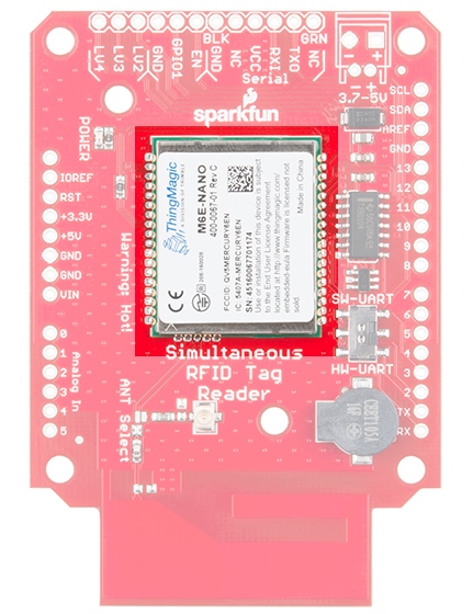
The M6E-NANO works with common, low cost, passive, Gen2 UHF tags available from a variety of online vendors in a variety of shapes and sizes. We offer two tags, with and without adhesive backing. Both have 64 bytes of user writable memory.
This module runs at 5V and pulls its power from the 5V lines on the breakout board.
Serial Interface
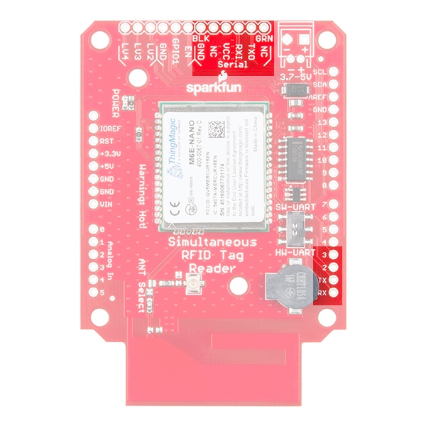
The M6E-NANO module is controlled via serial. There are two serial connections available: via a 6-pin FTDI compatible connection and via the TX/RX pins on the Arduino shield.
Serial Selection Switch
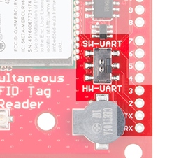
A switch is provided to allow the user to select between Hardware Serial (HW-UART) and Software serial (SW-UART) pins on the Arduino-compatible footprint. Set this switch to SW-UART for all the example Arduino sketches provided below. If you are using an external USB to Serial connection this switch has no effect.
Enable and GPIOs
The M6E uses an internal DC to DC converter to provide itself with power. When the EN (enable) pin is pulled low the DC/DC converter is turned off and the module does a hard reset. EN can be left unconnected for normal operation.
The NANO uses a SAMD21 as its main processor. The LV2, LV3, and LV4 pins are connected to the GPIOs on the SAMD21. They can be set high/low but these features are not yet supported in software.
Buzzer
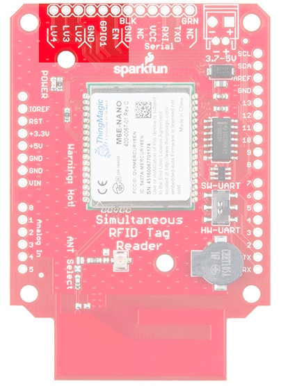
A buzzer is connected to pins 9 and 10 and can be PWM controlled to produce a tone.
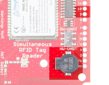
The most common use is to beep when a new tag is detected. This makes range testing much easier as you can bring the tag into the field until you hear a beep.
JP1
A jumper on the rear of the board labeled JP1 is closed by default allowing the board to be powered via the USB to Serial converter.

By default the JP1 Jumper is closed allowing the USB to Serial converter provide power to the SRTR. Cut this jumper if you are powering the board with a LiPo battery or other external power supply. This will isolate the USB to Serial converter for communication only.
Ground Plane Heatsink
The SRTR has a large ground plane heatsink on the bottom of the shield.
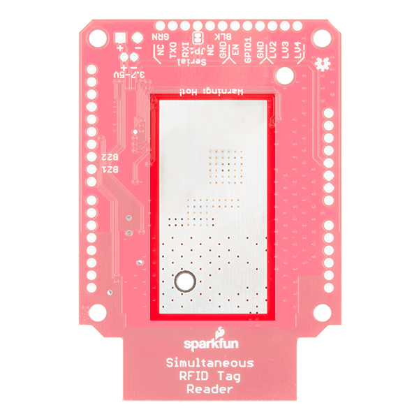
The exposed copper pour along with two mounting holes allow the connection to a heatsink such as a chassis or block of metal. Your board should have also shipped with a piece of Thermal Gap Filler. Please check out the Thermal Considerations section for more information on this.
Antennas
The Nano M6E is a powerful transmitter capable of outputting up to 27dBm! That's a lot.
The SRTR comes with an on-board PCB trace antenna, and a u.FL connector for an external antenna. An ANT Select solder jumper allows users to select between the two options. Check the Using an External Antenna section for more information on this.
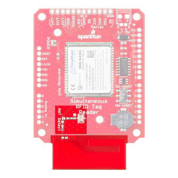
The PCB antenna is an excellent way to begin to experiment with UHF RFID. You’ll be able to read and write tags that are within 1 to 2 feet of the PCB. If you would prefer to use an external antenna, you can find more information in the Using an External Antenna section.