Smart Home Expansion Kit for Arduino 101
 D___Run___
 Experiment 6: Controlling a Solenoid Valve With a MOSFET
Introduction
A big part of home automation is being able to control devices and circuits that operate at a lot higher voltage and current than a standard microcontroller. If you hooked up the GPIO pin of an Arduino 101 board to 12 volts, you would destroy your board. So, how is it done?
The answer is using something called a MOSFET! In this experiment we will use the Arduino 101 and Blynk to control a solenoid valve using a MOSFET and build a BLE-controlled sprinkler timer! Hope you brought your swimsuit because you are going to need it!
Parts Needed
You will need the following parts:
- 1x Breadboard (From your Arduino 101 SIK)
- 1x Arduino 101 Board (From your Arduino 101 SIK)
- 1x MOSFET
- 1x Solenoid Valve
- 2x Female Disconnects
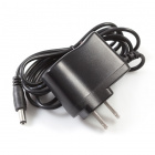
- 1x 12V Wall Wart Power Adapter
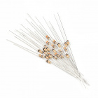
- 2x 10k Ohm Resistor (From your Arduino 101 SIK)
- 8x Jumper Wires (From your Arduino 101 SIK)
Didn't Get the Around-the-Home Expansion Kit?
If you are conducting this experiment and didn't get the Around-the-Home Expansion Kit, we suggest using these parts:


Suggested Reading
Before continuing with this experiment, we recommend you be familiar with the concepts in the following tutorials:
- Light-Emitting Diodes --- Learn more about LEDs
- Switch Basics --- Learn more about buttons and switches
Introducing the MOSFET
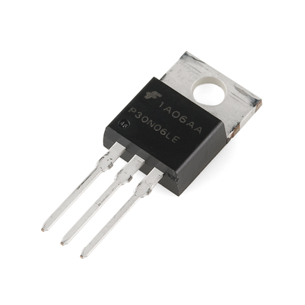
In Experiment 11 from the SparkFun Inventor's Kit for the Arduino 101 experiment guide, you learned about using transistors and that they were like a switch that allows you to control larger loads of electricity with a much smaller current and/or voltage in a safe way, protecting your Arduino board from harm. A MOSFET does the same thing, and, in fact, we are using them the same way. They are hooked up differently, and the MOSFET can handle a much larger load than the puny transistor from your Inventor's Kit.
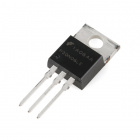
Similar to the transistor, the MOSFET has three legs, but they have different names. If you place the MOSFET on the table with its flange side down and the legs pointing toward you, the pins are named as follows:
LEFT = Gate
MIDDLE = Drain
RIGHT = Source
Here is a reference image from the datasheet of the MOSFET we use in this kit:
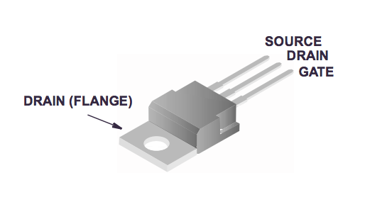
To use the MOSFET you connect the Gate pin to a GPIO pin of a microcontroller --- in this case, your Arduino 101 board. The Drain is connected to the load's ground line, and the Source is connected to the system's Ground. When you energize, or pull the Gate HIGH, you let current through the MOSFET in through the Drain and out through the Source.
Thank you, Pete! Now back to your regularly scheduled programming!
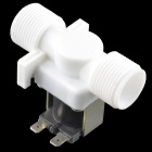
Introducing the Solenoid Valve
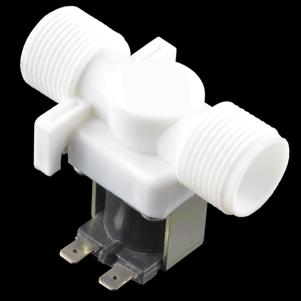
Have you ever wanted to control the flow of a liquid using your computer or microcontroller? Yeah, us too! Well, here’s how: This is a 12V solenoid-controlled fluid valve. Simply connect a fluid source to the ¾" threaded inlet, and it will interrupt the flow until 12V is applied to the fast-on connectors on the solenoid.
By now you are probably connecting the dots as to why we also covered the MOSFET in that this valve functions using 12 volts, much too high to run through the GPIO pins of the Arduino 101 board. So, we will control this valve using the MOSFET and a 12V wall power supply.
When you connect this valve to 12 volts and Ground, the coil inside of it gets energized and pulls the valve open, allowing water that is under pressure to flow through it. Yep, that's right; for this valve to work, the water you are controlling needs to be under pressure. Not a problem for our application, as we are going to be building a sprinkler timer.
Connecting the Valve
"But, wait!" you may be asking, "How do I connect the valve to the rest of my circuit with those funny tabs?" Great question! We have included female disconnects that are pretty easy to add to jumper wires if you have a pair of pliers. Grab two jumper wires, two disconnects and your pliers, and let's build some custom jumper wires!
First start by sliding the female disconnect over one end of a jumper wire and press it as far as it will go. Then take your plier and crimp the disconnect onto the wire as hard as you can. We don't want the disconnect coming loose!
OK, that's it! Rinse and repeat for the second wire, and you should be good to go! Give your new disconnects a good test to make sure they will stay on the wire, and let's jump to the next steps.
Hardware Hookup
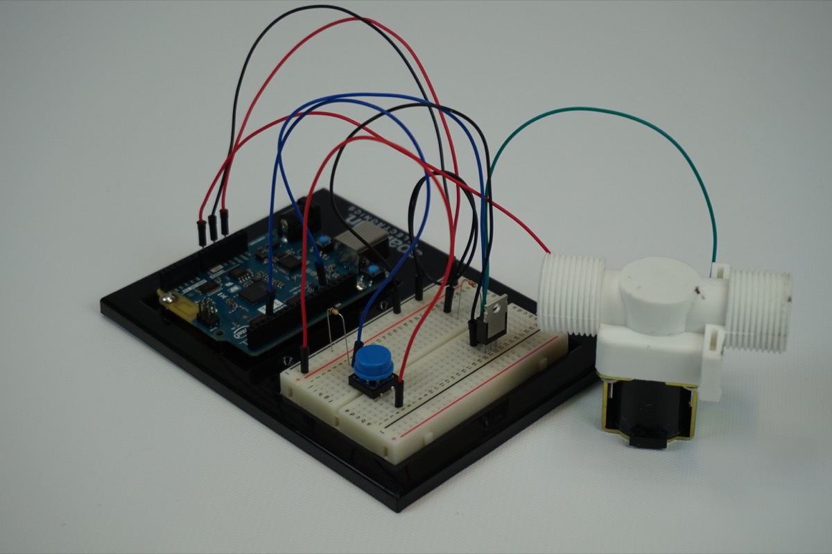
Ready to start hooking everything up? Check out the wiring diagram below to see how everything is connected.
Wiring Diagram for the Experiment
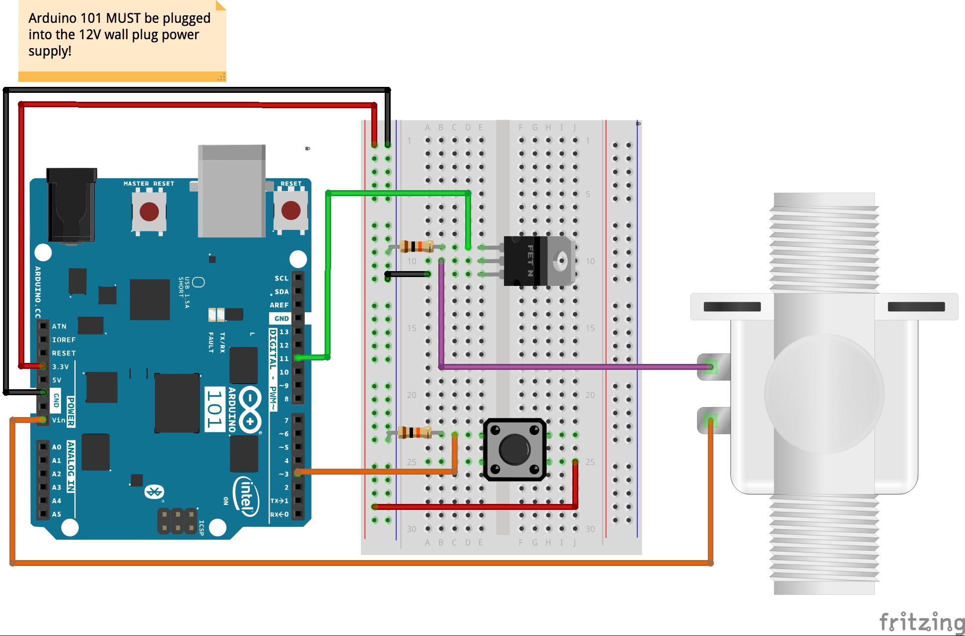
Powering Your Project
When you start to build projects that use either higher current or voltage levels that exceed the standard operational levels that the Arduino 101 board can source from a USB cable, an alternative power supply will be needed. In fact, you have probably been dangerously close using the BLE and controlling circuits in the past four experiments.
In this case, we are using a solenoid valve that requires 12V to operate. The good thing is that the Arduino 101 board can be powered by an external power supply in the range of 7 to 14 volts through the barrel jack on the board. This kit includes a 12V power supply just for this reason!
Once you plug the Arduino 101 board into the 12V power supply, it will turn the board on, and you will have access to both the 5V and 3.3V power rails. But now your VIN pin will be 12V, and you can use that pin to power your solenoid!
Build Your Blynk App
This Blynk app is a little more complicated than in your previous projects. You will be using the Time Input widget to set the Real-Time Clock (RTC) on the Arduino 101 board. For more details on that, or a quick refresher, you can reference Experiment X of the SIK guide for the Arduino 101 board. This app will allow you to set the RTC and then set a timer to control the solenoid valve to open and close at given time intervals to water your favorite tomato plant --- or to control a water feature in your backyard.
This capitalizes on the internal memory and global variables so that you can connect to your project, set the times, disconnect and not worry about it.
As with all of the Blynk apps that use the Arduino 101 board, add the BLE widget and open the settings to connect your phone to the board.
Once you have added the BLE widget, we will add two different Time Input widgets. These widgets allow for you to set the time and create timers that schedule functions to happen at given times. We will first add both Timer Input widgets to your app. These cannot be resized, so place them in a way that makes sense to you.

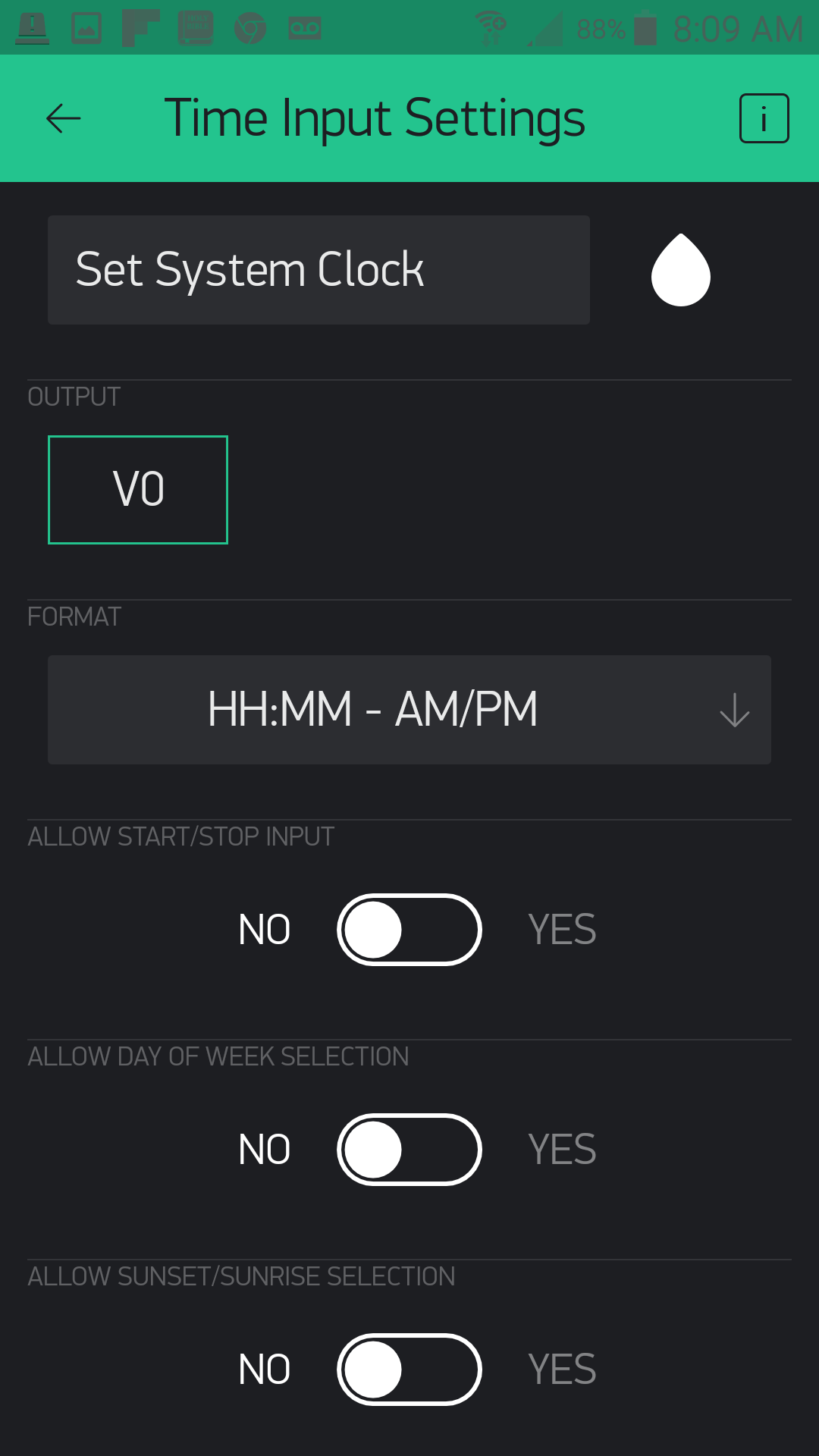
Open one of the Time Input widgets and name it "Set System Clock" and its output to pin V0. Set the format as "HH:MM - AM/PM". We changed no other setting after that. This input is what you will use to set the RTC to your current time. You will need to do this any time that your 101 loses power, or is reset.
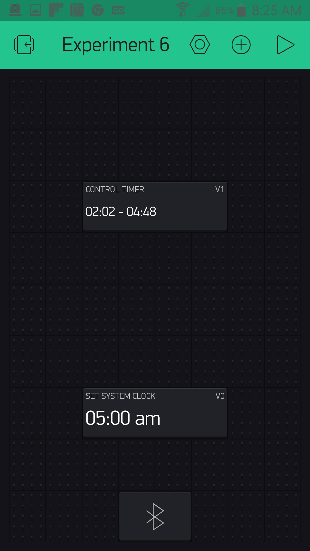
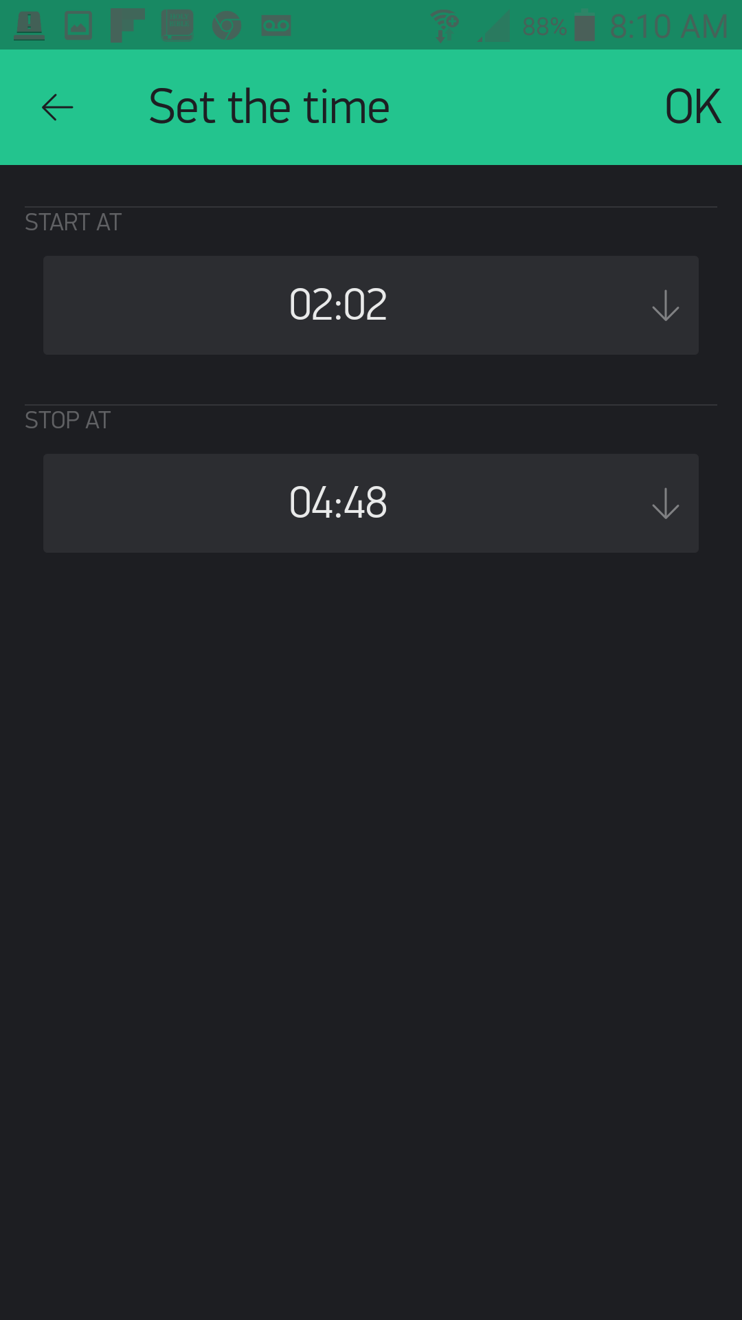
Open the second Time Input widget. This will be the timer control input. We labeled ours "Control Timer" and set the output to pin V1 with the format as "HH:MM". The only other setting we changed was to allow Start and Stop times.

That's it! Your completed app should look something like this when you run it:
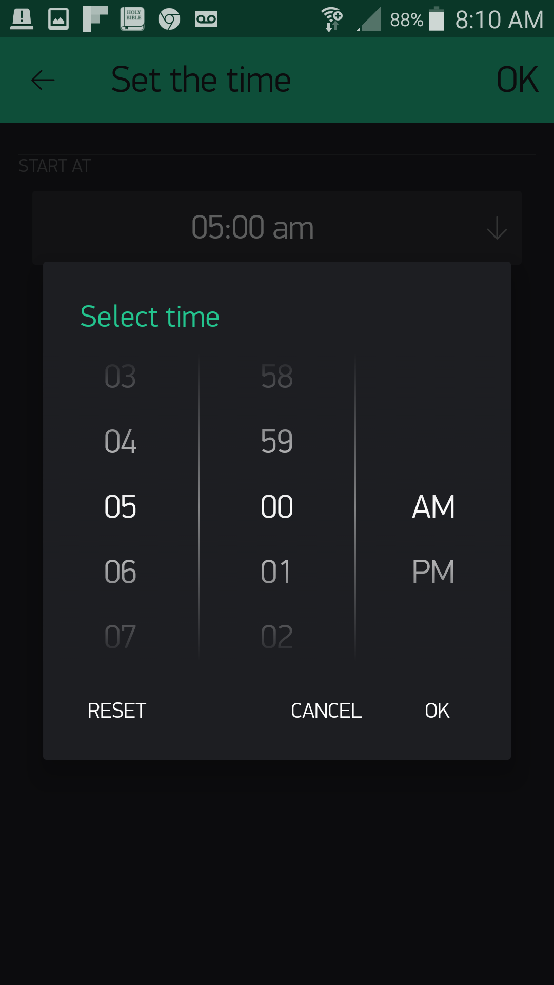
When you click on your "Set System Clock" it will allow you to set the time as shown below.
Your control timer interface will look something like this:
Now, let's get the Arduino sketch uploaded so that you won't have to worry about watering your lawn tomorrow.
Upload Your Sketch
Open the Arduino IDE software on your computer. Coding in the Arduino language will control your circuit.
You can type out or copy and paste the following code into the Arduino IDE. Hit upload, and see what happens!
language:cpp
/********************************************************************************
SparkFun Around-The-Home SIK Expansion Kit, Experiment 6
SparkFun Electronics
Product URL

Set the time of the Real-time-clock on the Arduino 101 using Blynk then set a timer to control a solenoid valve to control your sprinkers.

This example is written by: Derek Runberg, Educational Technologist

This sketch was written by SparkFun Electronics, with lots of help from the Arduino community.
This code is completely free for any use.

View circuit diagram and instructions at:https://learn.sparkfun.com/tutorials/around-the-home-expansion-kit

********************************************************************************/

/* Comment this out to disable prints and save space */
#define BLYNK_PRINT Serial
#include <CurieTime.h>
#include <BlynkSimpleCurieBLE.h>
#include <CurieBLE.h>

BLEPeripheral  blePeripheral;

// You should get Auth Token in the Blynk App.
// Go to the Project Settings (nut icon).
char auth[] = "YOUR_AUTH_TOKEN";


int startHour, startMinute, stopHour, stopMinute;
int override = false;

const int BUTTON_PIN = 3;
const int VALVE_PIN = 11;

void setup()
{
  Serial.begin(9600);

  blePeripheral.setLocalName("Exp_06");
  blePeripheral.setDeviceName("Exp_06");
  blePeripheral.setAppearance(384);

  pinMode(BUTTON_PIN, INPUT);
  pinMode(VALVE_PIN, OUTPUT);
  Blynk.begin(blePeripheral, auth);

  blePeripheral.begin();
  attachInterrupt(3,testValve,CHANGE);
}

void loop()
{
    //if start time matches...
    if (hour() == startHour && minute() == startMinute) {
      digitalWrite(VALVE_PIN, HIGH);
    }
    //if stop time matches...
    if (hour() == stopHour && minute() == stopMinute) {
      digitalWrite(VALVE_PIN, LOW);
    }
  blePeripheral.poll();
  Blynk.run();
}

void testValve(){
  if(digitalRead(BUTTON_PIN) == HIGH){
    digitalWrite(VALVE_PIN, HIGH);
    Serial.println("test fire");
  }
  else{
    digitalWrite(VALVE_PIN, LOW);
  }
}

//set clock event
BLYNK_WRITE(V0) {
  TimeInputParam t(param);

  // Set the RTC on the Arduino 101
  setTime(t.getStartHour(), t.getStartMinute(), 0, 2, 2, 2015);
}

//event function for timer
BLYNK_WRITE(V1) {
  TimeInputParam t(param);

  // Process start time
  if (t.hasStartTime())
  {
    startHour = t.getStartHour();
    startMinute = t.getStartMinute();
  }

  // Process stop time
  if (t.hasStopTime())
  {
    stopHour = t.getStopHour();
    stopMinute = t.getStopMinute();
  }
}
Code to Note
#include <CurieTime.h>
The Arduino 101 board, and specifically the Intel® Curie chip that is on the board, has its own Real-Time Clock (RTC), which we end up using in this project. To interact with the RTC, we need to add the CurieTime library that is included with Arduino when you install the Arduino 101 board definitions.
int startHour, startMinute, stopHour, stopMinute;
We create a number of empty global variables to start with in a bit of a different way. If you are going to create a number of variables of the same data type, you can actually list them out separated by commas in this fashion.
language:cpp
const int BUTTON_PIN = 3;
const int VALVE_PIN = 11;
We created two global constants to store the pin numbers for each component.
language:cpp
//set clock event
BLYNK_WRITE(V0) {
  TimeInputParam t(param);

  // Set the RTC on the Arduino 101
  setTime(t.getHour, t.getMinute, t.getSecond, 2, 2, 2015);
}
When you input a time into the Clock Set widget in your app, that time is written to the virtual pin 0 or V0. We then create a TimeInputParam object called t. We then set the RTC of the Arduino 101 board using the setTime() function and pass it the time parameters from t.
language:cpp
     //if start time matches...
     if(hour() == startHour && minute() == startMinute){
     digitalWrite(VALVE_PIN,HIGH);
    }
     //if stop time matches...
     if(hour() == stopHour && minute() == stopMinute){
     digitalWrite(VALVE_PIN,HIGH);
   }
We use a series of if() statements to check against the current time and the start time variables captured from the start and stop time values received over pin V1 from the Control Timer widget and stored in the global start and stop variables.
language:cpp
 BLYNK_WRITE(V1) {
  TimeInputParam t(param);

  // Process start time
  if (t.hasStartTime())
  {
   startHour = t.getStartHour();
   startMinute = t.getStartMinute();
  }

 // Process stop time
 if (t.hasStopTime())
 {
  stopHour = t.getStopHour();
  stopMinute = t.getStopMinute();
 }
}
We capture the start and stop times over virtual pin V1 from the Control Timer widget. We again create a local TimeInputParam object, which holds the time data from pin V1. Then, using a series of if() statements checking for a start and stop time, we store those start and stop times in our global variables.
What You Should See
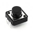
You shouldn't actually see anything happen right away. If you press down on the button in the circuit, which is the manual override, it should open the valve. If you press the button again, the valve will close.
If you connect to the Blynk app, you can set the Real-Time Clock on the Arduino 101 board, as well as a scheduled start and stop time. Set the time for your local time and then a start time about three minutes or so from that time, with a stop time five minutes later. From here you should be able to close the Blynk app as long as the Arduino 101 board stays powered up. You can do this because the Real-Time Clock on the Arduino 101 was set by the Blynk app, and all of the control logic for the watering system is on the Arduino side of the sketch.
The valve should turn on in three minutes and then off again in five more! No more forgetting that your sprinklers are running!
Troubleshooting
Blynk Shortcut!
If you are having troubles duplicating the functionality above in the Blynk app, scan this QR code with Blynk to get a clone of this experiment!

Program Not Uploading
This happens sometimes; the most likely cause is a confused serial port. You can change this in Tools > Serial Port >
Also, if you get a Timeout error or the IDE could not find your 101 board, try pressing the Master Reset button on the 101, wait around 10 seconds and try re-uploading your sketch.
Still No Success
A broken circuit is no fun. Send us an email, and we will get back to you as soon as we can: techsupport@sparkfun.com