Sound Detector Hookup Guide
 Byron J.
Looking Closer
Three Outputs?
The Sound Detector has 3 separate outputs. It's easiest to see what each is doing with a graph. The following illustrates how the sound detector responds to a series of sound pulses.
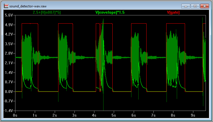
This shows the output voltages over time.
- The dark green trace is the audio output of the sound detector. The audio voltage directly from the microphone is found at this output.
- The light green trace is the envelope output. This analog voltage traces the amplitude of the sound. Of particular interest, notice that the third pulse gets noticeably louder as it goes.
- Finally, the red line is the gate output. This output is low when conditions are quiet and goes high when sound is detected.
How It Works
Having examined the outputs, lets also take a quick walk through the schematic, to gain an understanding of how each stage works.
First Stage
The first section of the circuit is an electret microphone capsule. This portion of the circuit borrows from the Electret Microphone breakout board.
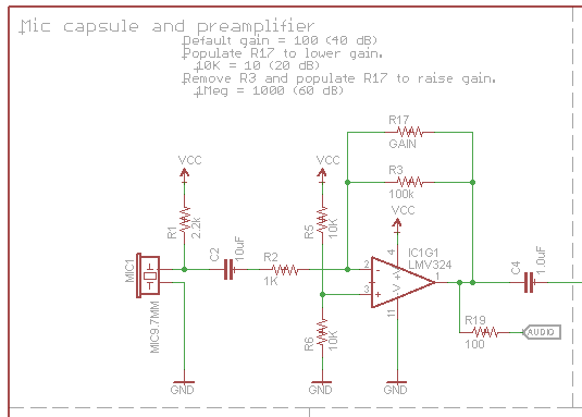
The capsule is biased by the supply voltage through R1, and it outputs an AC voltage that is riding a DC offset of approximately 1/2 the supply voltage.
The output from the capsule is an extremely small voltage, so the signal from the capsule is amplified by IC1G1, an operational amplifier stage. By default, the preamplifier has an arithmetic gain of 100 (20 dB), and the gain can be adjusted by populating R17 (which we'll examine in detail on the next page).
The audio output is DC coupled, riding one half the supply voltage, so it can be directly connected to the ADC of a microcontroller. In perfectly quiet conditions, it will ideally read 1/2 full scale, or 512 on a 10-bit converter.
Second Stage
The second stage of the circuit is an envelope follower.
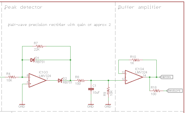
IC1G3 forms an opamp-based precision rectifier. This stage implements the equation
if(Vin > 0)
    Vout = 0;
else
    Vout = Vin * -2.2
The opamp inverts and amplifies the signal. When it's output swings high, D2 turns on, and charges C1. When the opamp output is high or not swinging, D2 is turned off, and C1 discharges through R9. Thus, C1 tracks the peaks of the input signal.
IC1G4 is a buffer amplifier, so external loads on the envelope pin won't change the C1's charge/discharge behavior.
This results in a signal that tracks the peak amplitude of the input signal. A louder sound will result in a higher voltage on the Envelope pin. As with the audio pin, the envelope can be connected to the ADC of a microcontroller.
Third Stage
The final stage implements a thresholded switch on the envelope signal.
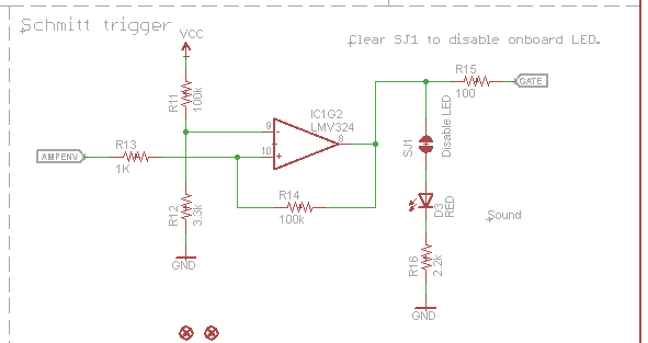
The Schmitt trigger watches the envelope signal, and toggles the output when the threshold is exceeded. A Schmitt trigger is a comparator that adjusts it's threshold voltage when the output switches, requiring a higher voltage to switch on than to switch off. This allows it to ignore some ripple in the input signal, like the ripple present in the output of the envelope follower stage.
The output of the Schmitt trigger is found on the Gate pin. You can connect it to a digital input. We'll use it to trigger interrupts in the software example.
Outputs
Each of the three output signals is present on the .1" header at the edge of the board. They are active simultaneously. If you aren't using one in your particular application, simply leave that pin disconnected.