SparkFun AS3935 Lightning Detector Hookup Guide (v20)
 Elias The Sparkiest
 Introduction
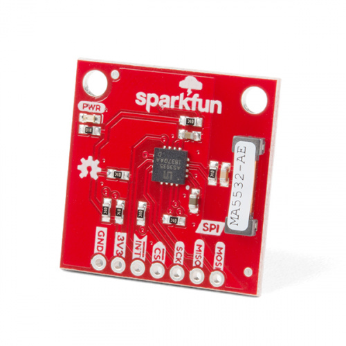
The SparkFun AS3935 Lightning Detector adds lightning detection to your next weather station or to your next bike ride. Are you worried about the looming clouds in the distance, how far away is that storm exactly? The lightning detector can tell you the distance to the front of the storm 40 km away with an accuracy of 1km. It has false positive rejection and comes with many configurable features. To get at those features we have written a library that gives you access to settings such as storm sensing sensitivity, when detecting indoors vs outdoors, or the number of lightning strikes needed to trigger an interrupt! Revision 2.0 of the board is SPI only*, with the caveat that if you wanted to use I²C, all the parts are there but it is NOT supported by SparkFun.
Required Materials
To follow along with the example code used in this tutorial, you will also need the following materials. You may not need everything though depending on what you have. Add it to your cart, read through the guide, and adjust the cart as necessary.


Tools
Depending on your setup, you will may need a soldering iron, solder, and general soldering accessories.


Suggested Reading
We would also recommend taking a look at the following tutorials if you aren't familiar with them.
Serial Peripheral Interface (SPI)
How to Work with Jumper Pads and PCB Traces
RedBoard Qwiic Hookup Guide
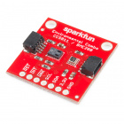
Hardware Overview
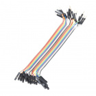
Power
You can provide 3.3V through the through hole labeled 3V3 on the header along the side of the product. When the board is powered, the on board red power LED will turn on.
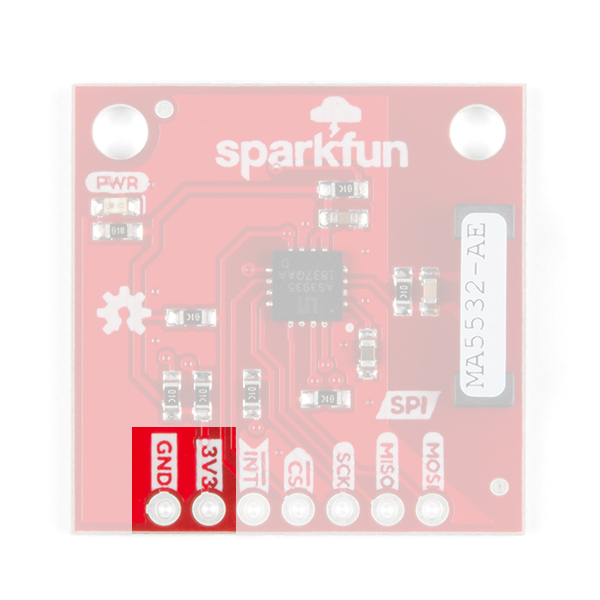
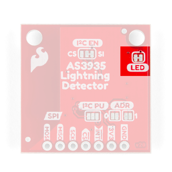
LED
There is one LED on the product and it will turn on when power is supplied to the board. You can disconnect this LED by cutting the jumper on the underside of the product labeled LED.
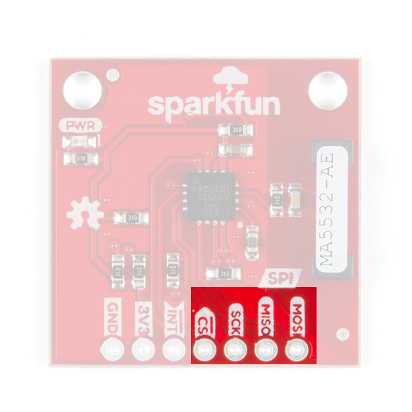
SPI
The SPI data pins on the header along the edge of the board are labeled with the respective functions necessary for using SPI: MOSI, MISO, CS, and SCK. We'll walk through how to use these pins in the example code below with Example 1-Lightning Basics.
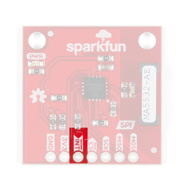
Interrupt Pin
The interrupt pin goes HIGH when the lightning detector has sensed an event, whether it's lightning, a disturber, or noise. Make sure to connect to this pin to check if there is an event detected.
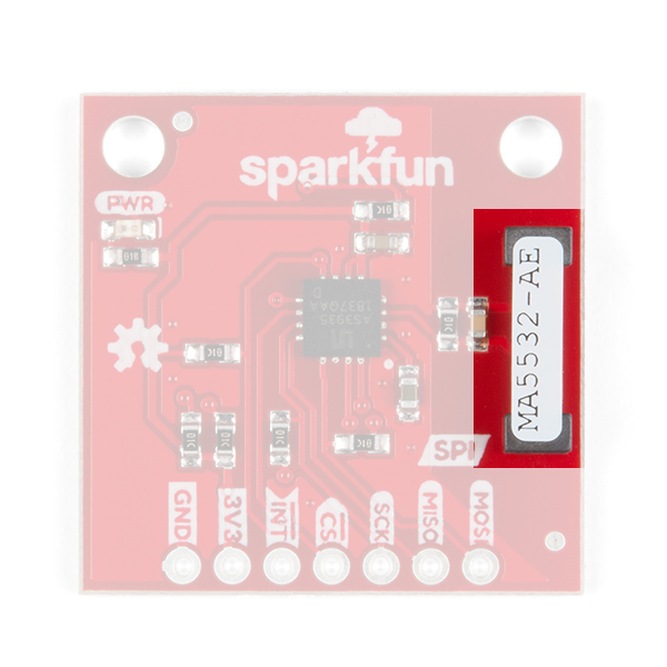
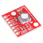
Antenna
The largest part on the SparkFun Lightning Detector is lightning antenna. Keep the area around the antenna free for optimal lightning detection.
Jumpers
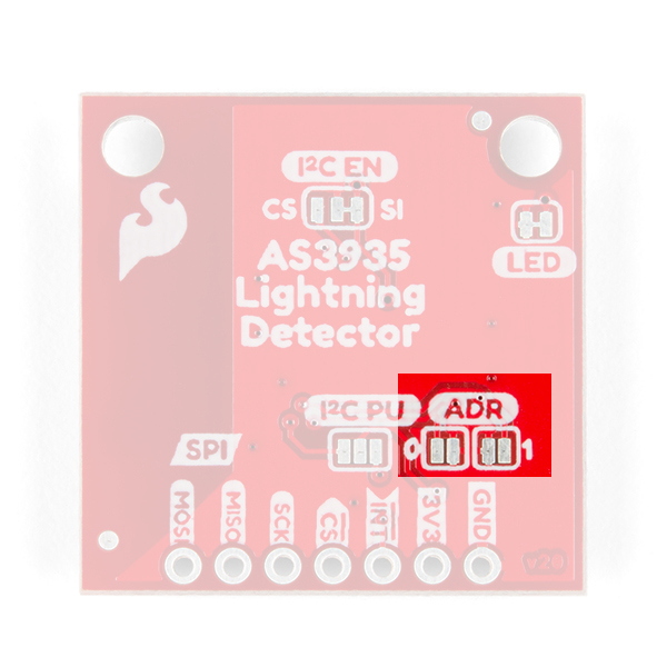
There are four jumpers on this product all on its underside. Starting at the lower left is the triple pull-up jumper labeled I2C PU, used for the I²C data lines (check section: A note on I²C below). If you have many I²C devices chained together, you will need to leave these jumpers open.
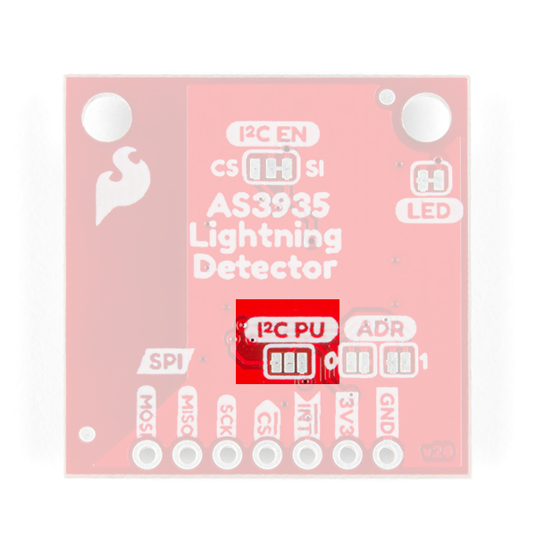
Next to the I2C PU jumper are two address jumpers labeled ADR that allow you to change the SparkFun Lightning Detector's I²C address. The default I²C address is 0x03 but it can be changed to two other addresses: 0x02, 0x01.
In the upper right is the power LED disconnect jumper; cut this to disconnect the red power LED.
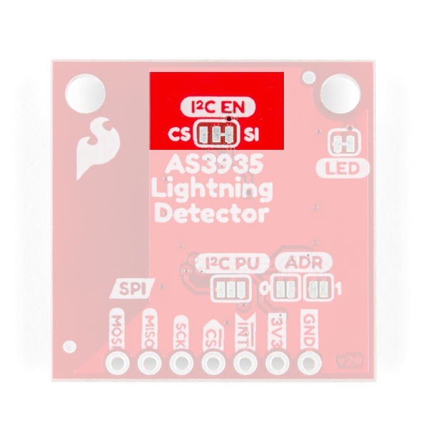
Finally towards the top is the I²C jumper which does two things: grounds the CS pin and enables I²C. SparkFun does not support I²C on this particular product (check section: A note on I²C below).
A Note on I²C
The SparkFun Lightning Detector's original design supported I²C but there were issues raised by a small percentage of customers who purchased this product with regards to its' reliability. This issue was followed up with an investigation by our engineers and unfortunately, we decided we could not support it officially. However, if you want to use it, all of the goods are there. Just know SparkFun won't be supporting problems that may arise with its' use.
To enable I²C: close the CS side of the I2C EN jumper and cut the SI side. Then close the right side of the I2C PU jumper. See jumpers above for pictures. You'll have to dig into the datasheet to see which lines are the I²C data lines. Happy Hacking!
False Positives and Noise
There are a number of sources that can cause false positives but the lightning detector itself can reliably filter these out by default. If not, there are a number of settings you can configure easily with SparFun's Lightning Detector library to increase the chip's robustness to noise and false positives (see Example2 More Lightning Features SPI). However, it can help to know some potential sources of noise: fluorescent lighting, microwave ovens, smartphone and smartwatch displays, DC-DC converters, refrigerators, and/or things that can switch large voltages in general.
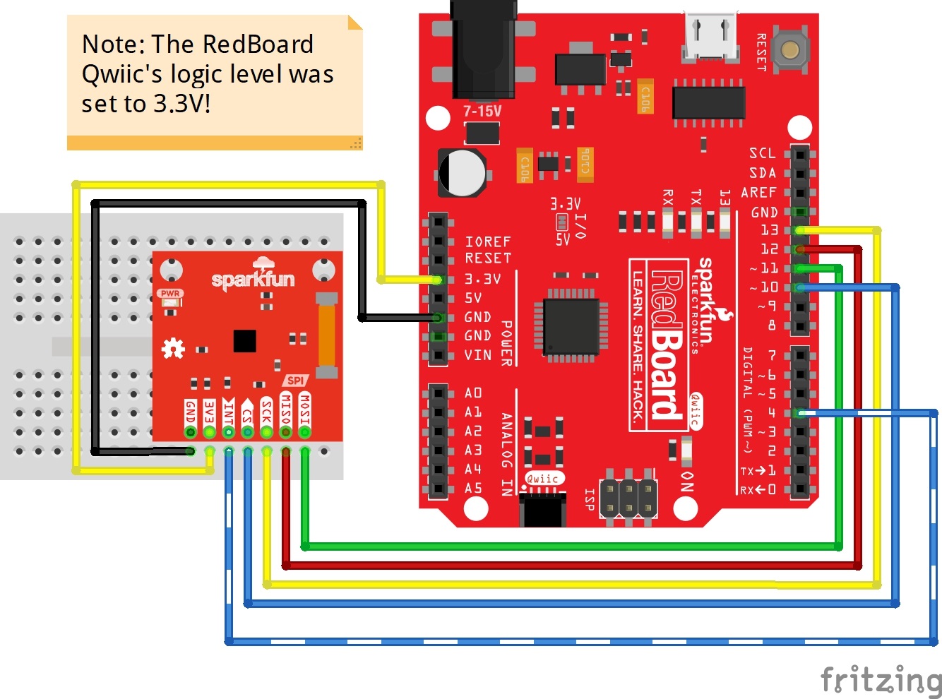
Hardware Assembly

For this you'll have to solder break away headers to the header on the SparkFun Lightning Detector. After plugging that into your breadboard, you'll wire the RedBoard Qwiic to the Lightning Detector with the following order.
| RedBoard Qwiic (Set to 3.3V Logic) | SparkFun Lightning Detector |
|---|---|
| 3.3V | 3.3V |
| GND | GND |
| 13 | SCK |
| 12 | MISO |
| 11 | MOSI |
| 10 | CS |
| 4 | INT |
Arduino Library Installation
If you've never connected an CH340 device to your computer before, you may need to install drivers for the USB-to-serial converter. Check out our section on How to Install CH340 Drivers for help with the installation.
We've provided a library for the SparkFun Lightning Detector that configures every available setting the IC offers. Some of the features include modifying the sensitivity of the antenna, whether you're inside or outside, fine tuning when the IC triggers an interrupt, or modifying the resonance frequency of the antenna. You can search the Arduino Library Manager for "SparkFun Lightning Detector", or you can click the button below to get the library and install it manually. Finally, you can also download it manually from the GitHub Repo.
Example 1 - Basic Lightning SPI
The example below will start with the basic functionality in Example1_BasicLightning_SPI.ino. Open the example up to follow along.
Example 1 - Basic Lightning SPI
At the very top, we have a few defines that will help us to distinguish what sort of event the SparkFun Lightning Detector has sensed. There are three possible "events". The first of course is lightning, but we may also get a false lightning event called a disturber, and finally we may hear noise. Also of note are the noise and disturber variables. We'll talk about those farther down in the main loop.
language:c
#include <SPI.h>
#include <Wire.h>
#include "SparkFun_AS3935.h"

#define INDOOR 0x12
#define OUTDOOR 0xE
#define LIGHTNING_INT 0x08
#define DISTURBER_INT 0x04
#define NOISE_INT 0x01

SparkFun_AS3935 lightning;

// Interrupt pin for lightning detection
const int lightningInt = 4;
int spiCS = 10; //SPI chip select pin

// This variable holds the number representing the lightning or non-lightning
// event issued by the lightning detector.
int intVal = 0;
int noise = 2; // Value between 1-7
int disturber = 2; // Value between 1-10
By default the SparkFun Lightning Detector is set to be run inside because I'm assuming you're at your computer running this code. If you're outside change the parameter to OUTDOOR.
language:c
void setup()
{
  // When lightning is detected the interrupt pin goes HIGH.
  pinMode(lightningInt, INPUT);

  Serial.begin(115200);
  Serial.println("AS3935 Franklin Lightning Detector");

  SPI.begin();

  if( !lightning.beginSPI(spiCS, 2000000) ){
    Serial.println ("Lightning Detector did not start up, freezing!");
    while(1);
  }
  else
    Serial.println("Schmow-ZoW, Lightning Detector Ready!");

  // The lightning detector defaults to an indoor setting at
  // the cost of less sensitivity, if you plan on using this outdoors
  // uncomment the following line:
  //lightning.setIndoorOutdoor(OUTDOOR);
}
In the main loop the interrupt pin is monitored for a lightning event from the Lightning Detector. If the interrupt pin goes HIGH we check whether this event is lightning, a disturber, or noise with the lightning.readInterruptReg() function call. Each of these events are printed out in the serial window at 115200 baud. If lightning is detected, then we check the distance to the storm with lightning.distanceToStorm() and print that out to the window. There are two other possibilities: noise and disturber. If you see a lot of noise or disturbers check the section False Positives and Noise above to help guide you to reduce the noise in your environment. We can also increase the SparkFun Lightning Detector's robustness to noise with the lightning.setNoiseLevel() function call. Likewise we can increase the SparkFun Lightning Detector's resistance to false lightning events with lightning.watchdogThreshold().
language:c
void loop()
{
   // Hardware has alerted us to an event, now we read the interrupt register
  if(digitalRead(lightningInt) == HIGH){
    intVal = lightning.readInterruptReg();
    if(intVal == NOISE_INT){
      Serial.println("Noise.");
      // Too much noise? Uncomment the code below, a higher number means better
      // noise rejection.
      //lightning.setNoiseLevel(noise);
    }
    else if(intVal == DISTURBER_INT){
      Serial.println("Disturber.");
      // Too many disturbers? Uncomment the code below, a higher number means better
      // disturber rejection.
      //lightning.watchdogThreshold(disturber);
    }
    else if(intVal == LIGHTNING_INT){
      Serial.println("Lightning Strike Detected!");
      // Lightning! Now how far away is it? Distance estimation takes into
      // account any previously seen events in the last 15 seconds.
      byte distance = lightning.distanceToStorm();
      Serial.print("Approximately: ");
      Serial.print(distance);
      Serial.println("km away!");
    }
  }
  delay(100); // Slow it down.
}
When lightning is sensed you'll see the following in your Arduino serial window.

Example 2 - More Lightning Sensor Features SPI
In the following example we'll explore some of the other features available to you from the SparkFun Lightning Detector Arduino Library. This example actually functions exactly as the example above in that it monitors for a lightning event in the main loop; so we'll focus on the setup to see how it demonstrates different settings that you can set.
At the top we have a few more variable for a number of settings. The first two noiseFloor and watchDogVal holds the values for increasing the Lightning Detector's robustness against noise and false lightning events respectively. The following variable spike holds a value to further increase the robustness of the SparkFun Lightning Detector towards false events. Finally lightningThresh holds the value for the number of lightning events that need to occur before the SparkFun Lightning Detector alerts you.
language:c
// Values for modifying the IC's settings. All of these values are set to their
// default values.
byte noiseFloor = 2;
byte watchDogVal = 2;
byte spike = 2;
byte lightningThresh = 1;
The first function call lightning.maskDisturber(true) will stop the Lightning Detector from alerting you to any false events at all. We check that the setting was set correctly with lightning.readMaskDisturber()
language:c
lightning.maskDisturber(true);

int maskVal = lightning.readMaskDisturber();
Serial.print("Are disturbers being masked: ");
if (maskVal == 1)
    Serial.println("YES");
else if (maskVal == 0)
    Serial.println("NO");
The next two function calls increase the SparkFun Lightning Detector's robustness to noise with lightning.setNoiseLevel() and false lightning events with lightning.watchdogThreshold(). We give these function the values in the variables mentioned above: noiseFloor and watchDogVal. Just below each of these respective functions are functions that read back the settings we just set: lightning.readNoiseLevel() and lightning.readWatchdogThreshold().
language:c
lightning.setNoiseLevel(noiseFloor);

int noiseVal = lightning.readNoiseLevel();
Serial.print("Noise Level is set at: ");
Serial.println(noiseVal);

// Watchdog threshold setting can be from 1-10, one being the lowest. Default setting is
// two. If you need to check the setting, the corresponding function for
// reading the function follows.

lightning.watchdogThreshold(watchDogVal);

int watchVal = lightning.readWatchdogThreshold();
Serial.print("Watchdog Threshold is set to: ");
Serial.println(watchVal);
The next setting is a bit light on details in the datasheet but helps to increase the SparkFun Lightning Detector's ability to reject false positives by reducing the spike that is analyzed by the validation routine within the Lightning Detector. This will make the lightning detector less sensitive.
language:c
// Spike Rejection setting from 1-11, one being the lowest. Default setting is
// two. If you need to check the setting, the corresponding function for
// reading the function follows.
// The shape of the spike is analyzed during the chip's
// validation routine. You can round this spike at the cost of sensitivity to
// distant events.

lightning.spikeRejection(spike);

int spikeVal = lightning.readSpikeRejection();
Serial.print("Spike Rejection is set to: ");
Serial.println(spikeVal);
The lightning.lightningThreshold() function makes it possible to increase the number of lightning strikes that the lightning detector senses before it issues an interrupt. Possible settings are 1, 5, 9 , or 16 lightning strikes.
language:c
// This setting will change when the lightning detector issues an interrupt.
// For example you will only get an interrupt after five lightning strikes
// instead of one. Default is one, and it takes settings of 1, 5, 9 and 16.
// Followed by its corresponding read function. Default is zero.

lightning.lightningThreshold(lightningThresh);

uint8_t lightVal = lightning.readLightningThreshold();
Serial.print("The number of strikes before interrupt is triggerd: ");
Serial.println(lightVal);
Did you set too many settings and just want to get it back to default settings? Then the function lightning.resetSettings() will do just that.
As mentioned above this example code does exactly the same as the first example above but offers more settings to tailor your SparkFun Lightning Detector to your project.
More Example Code
If you're looking to tune the antenna's frequency of the SparkFun Lightning Detector then check out the Example 3- Tune Antenna SPI included in the SparkFun Lightning Detector Library. You'll need some method of reading a square wave of at least 4kHz: an oscilloscope, or logical analyzer. As a good starting point, we've found that the resonance frequency of our manufactured boards start at about ~496kHz. The datasheet specifies that the resonance frequency should be within 3.5 percent above or below 500mHz for optimal lightning detection. Our boards ship within less than one percent of that value.
Resources and Going Further
For more on the AS3935, check out the links below:
- Schematic (PDF)
- Eagle Files (ZIP)
- Datasheet (PDF)
- GitHub
- SparkFun AS3935 Lightning Detector Library
- Product Repo - Design files and more datasheets!
- SFE Product Showcase
Need some other weather sensing parts for your project? Check out some of the ones listed below.
Need some inspiration for your next project? Check out some of these related tutorials to sense your environment!
Si4707 Hookup Guide
Photon Remote Water Level Sensor
Qwiic Atmospheric Sensor (BME280) Hookup Guide
How to Make a Magic Mirror with Raspberry Pi
Or check out this related blog post.