SparkFun Auto pHAT Hookup Guide
Hardware Overview
Below, is an overview of the major hardware components on the Auto pHAT.
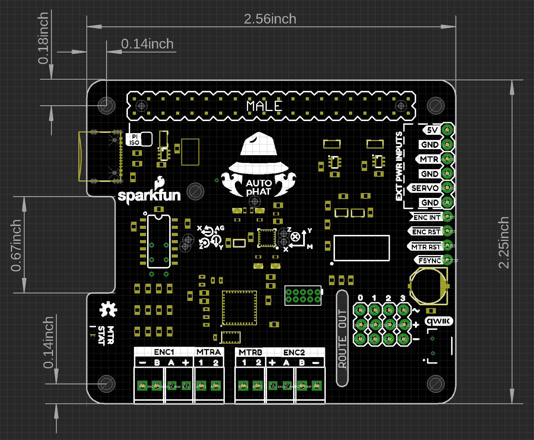
Dimensions
The overall dimensions of the Auto pHAT are 57mm x 65mm. For more details, users can check out the layout in the Eagle files. The board also features two cut-outs for the camera and display ribbon connections.
GPIO Connections
As the Auto pHAT is also intended to integrate with other HATs, it is important to know all of the pin being utilized to avoid conflicts. Below is a layout of all the GPIO pins being utilized by the hardware on the Auto pHAT. (*Click the following links, for more information on the GPIO mapping of the Raspberry Pi or Jetson Nano.)
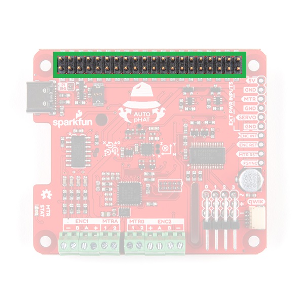
GPIO header connection on the top of the Auto pHAT.

GPIO header connection on the bottom of the Auto pHAT.
Raspberry Pi GPIO Map
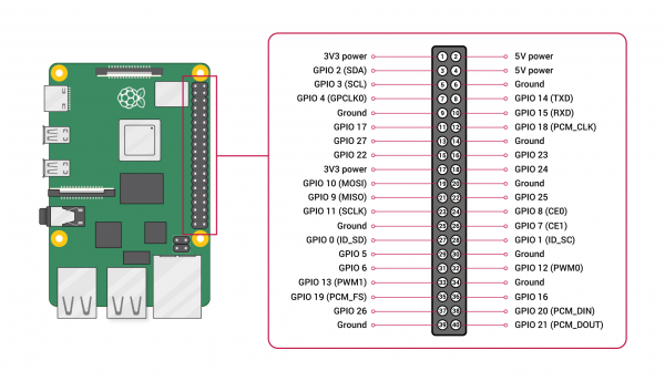 Standard GPIO layout on the Raspberry Pi.
 Image courtesy of the Raspberry Pi Foundation.
Power Connections
Power to the Auto pHAT is supplied through the GPIO pins; both 5V and 3.3V are utilized.
| Pin # | GPIO |
|---|---|
| 1 | 3.3V |
| 17 | 3.3V |
| 2 | 5V |
| 4 | 5V |
| 6 | GND |
| 9 | GND |
| Pin # | GPIO |
|---|---|
| 14 | GND |
| 20 | GND |
| 30 | GND |
| 34 | GND |
| 39 | GND |
Qwiic (I2C)
IMU (I2C)
| Pin # | GPIO | Function |
|---|---|---|
| 3 | GPIO 02 (SDA) | Qwiic (SDA) |
| 5 | GPIO 03 (SCL) | Qwiic (SCL) |
| 26 | GPIO 7 | Interrupt |
Encoder (I2C)
| Pin # | GPIO | Function |
|---|---|---|
| 3 | GPIO 02 (SDA) | Qwiic (SDA) |
| 5 | GPIO 03 (SCL) | Qwiic (SCL) |
| 7 | GPIO 4 | Interrupt |
Motor Driver (I2C)
| Pin # | GPIO | Function |
|---|---|---|
| 3 | GPIO 02 (SDA) | Qwiic (SDA) |
| 5 | GPIO 03 (SCL) | Qwiic (SCL) |
Servo Controller (I2C)
| Pin # | GPIO | Function |
|---|---|---|
| 3 | GPIO 02 (SDA) | Qwiic (SDA) |
| 5 | GPIO 03 (SCL) | Qwiic (SCL) |
Qwiic Connector
| Pin # | GPIO | Function |
|---|---|---|
| 3 | GPIO 02 (SDA) | Qwiic (SDA) |
| 5 | GPIO 03 (SCL) | Qwiic (SCL) |
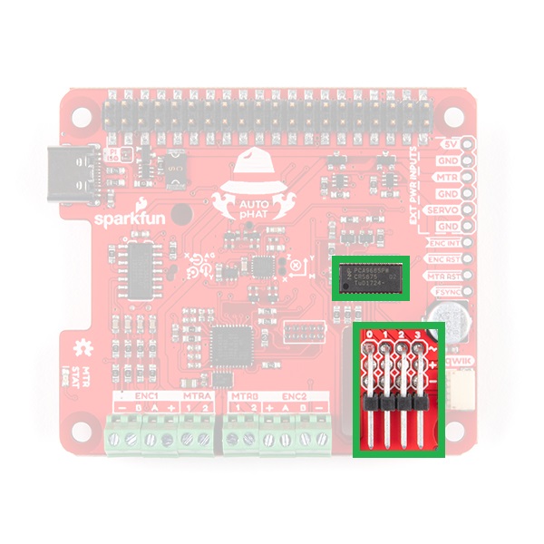
Servo Controller
The servo controller utilizes the same PCA9685 IC used on the Pi Servo pHAT; however, only the first 4 PWM channels are broken out. The PCA9685 provides I2C control over the 16-channels of 12-bit pulse width modulation (PWM); although only the first 4-channels are available on the Auto pHAT. The default I2C address for the servo controller on the Auto pHAT is 0x40.
| Characteristic | Description |
|---|---|
| Operating Voltage (VDD) | 2.3 V to 5.5 V (Hardwired: 5V) |
| Operating Temperature | -40°C to 85°C |
| PWM Outputs |
16 Totem pole outputs (Default: Open-Drain) Sink 25 mA or Source 10 mA (at 5V) Shared PWM frequency Supports hot insertion |
| PWM Frequency | 24Hz to 1526 Hz (Default (1Eh): 200Hz) |
| PWM Resolution | 12-bit (4096 steps of control) |
| Duty Cycle | 0% to 100% (adjustable) |
| Oscillator |
Internal: 25 MHz (Hardwired) External: 50 MHz (max.) input (unavailable) |
| I2C Address |
8 available hardware configurable addresses
|
Pi Servo Hat Hookup Guide
September 14, 2017
Pi Servo pHAT (v2) Hookup Guide
July 11, 2019
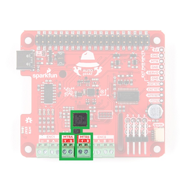
Motor Driver
The motor driver consists of the same PSoC4245 and DRV8835 as the Serial Controlled Motor Driver and Qwiic Motor Driver. The DRV8835 H-Bridge provides two drive outputs, each capable of 1.2A at steady state. The default I2C address for the motor driver on the Auto pHAT is 0x5D.
| Characteristic | Description |
|---|---|
| Operating Voltage (VDD) | 3 V to 11 V (Hardwired: 5V) |
| Drive Channels | 2 Channels |
| Drive Strength |
1.5A per channel (max.) 1.2A (steady state) |
| Drive Control |
127 levels of control Direction inversion on a per motor basis Global Drive enable |
| I2C Address |
10 available hardware configurable addresses
|
Thermal Management
An important consideration for the motor driver is the thermal load due to the current draw of the motors. In order to dissipate the heat, users can use our Theragrip Thermal Tape to attach Small Heat Sinks across the thermally conductive area on the bottom of the board. As the thermal plane doesn't promote natural convection well, users can add a fan to help dissipate the energy, as well.
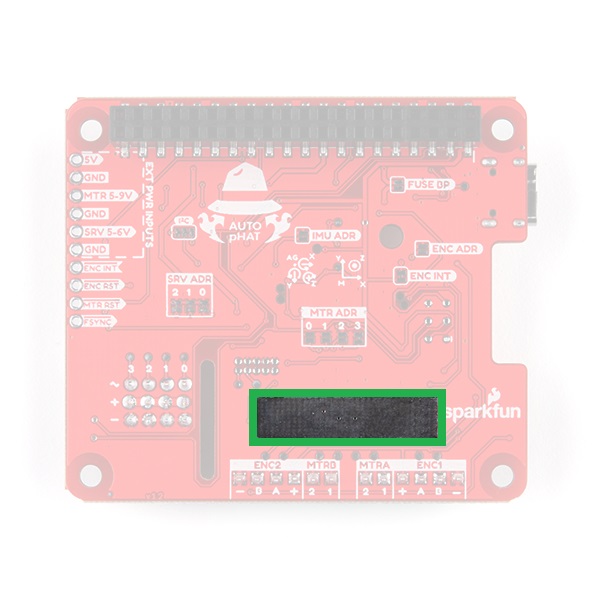
Thermally conductive area on the bottom of the Auto pHAT.
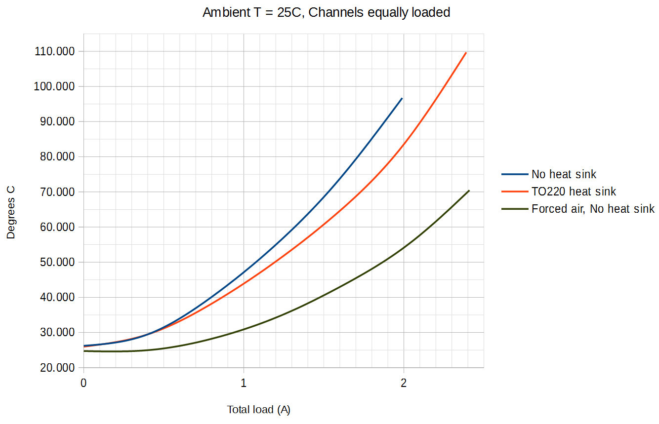
Temperature to total driver load curve.
Serial Controlled Motor Driver Hookup Guide
November 17, 2016
Hookup Guide for the Qwiic Motor Driver
September 19, 2019
Encoder Reader
At the heart of the encoder reader is an ATtiny84, which is utilized on our pseudo I2C devices. The encoder reader is based off of the Qwiic Twist, but is capable of reading two, separate quadrature encoders. The default I2C address for the servo controller on the Auto pHAT is 0x73.

9-DoF IMU
The 9-DoF (degree of freedom) IMU is the same ICM20948 IC used on the 9DoF IMU Breakout. It provides 10 unique measurements: 3 axes of acceleration, rotational rate, and magnetic strength data, as well as, internal temperature. Users should note the location of the IMU and the orientation of the axes (labeled on the board), when taking measurements. The default I2C address for the IMU on the Auto pHAT is 0x69.

| Characteristic | Description |
|---|---|
| Operating Voltage (VDD) | 1.71 V to 3.6 V (Hardwired: 1.8V) |
| Operating Temperature | -40°C to 85°C |
| Gyroscope |
Full Scale Ranges:
Sensitivity:
|
| Accelerometer |
Full Scale Ranges:
Sensitivity:
|
| Magnetometer |
Full Scale Range: ±4900 µT Sensitivity: .15 µT Output Data Rate: 100 Hz |
| I2C Address |
2 hardware configurable addresses:
|
Note: For more details on the ICM-20948 and its utilization as an IMU, check out the following hookup guide:
SparkFun 9DoF IMU (ICM-20948) Breakout Hookup Guide
June 27, 2019
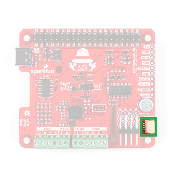
Qwiic Connector
A connector is provided for attaching other Qwiic devices.
Note: While most of our Qwiic devices should be compatible with a single board computer (SBC), not all have a supported Python package. Users who are unfamiliar with our Qwiic connect system, can check out the video below: