SparkFun Blocks for Intel® Edison - Pi Block
 Shawn Hymel
Using the Pi Block
To use the Pi Block, attach an Intel® Edison to the back of the board, or add it to your current stack. Blocks can be stacked without hardware, but it leaves the expansion connectors unprotected from mechanical stress.
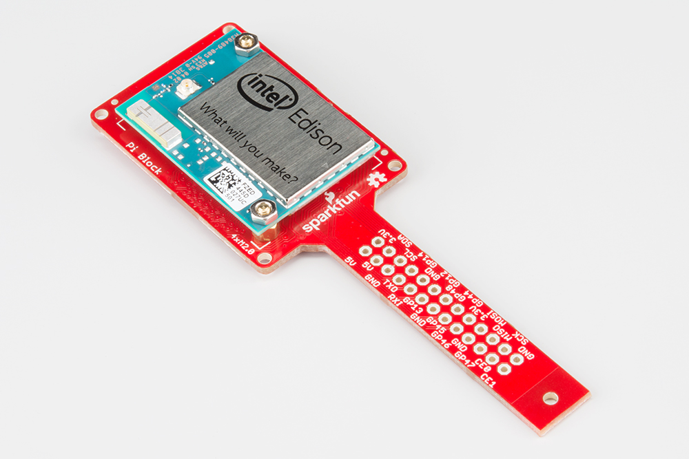
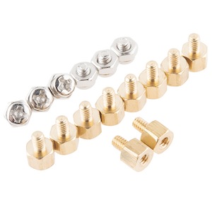
We have a nice Hardware Pack available that gives enough hardware to secure three blocks and an Edison.
You can put headers on the Edison side, which gives you easy access to the pin labels. Note that this pinout is mirrored from the Raspberry Pi Model B pinout.
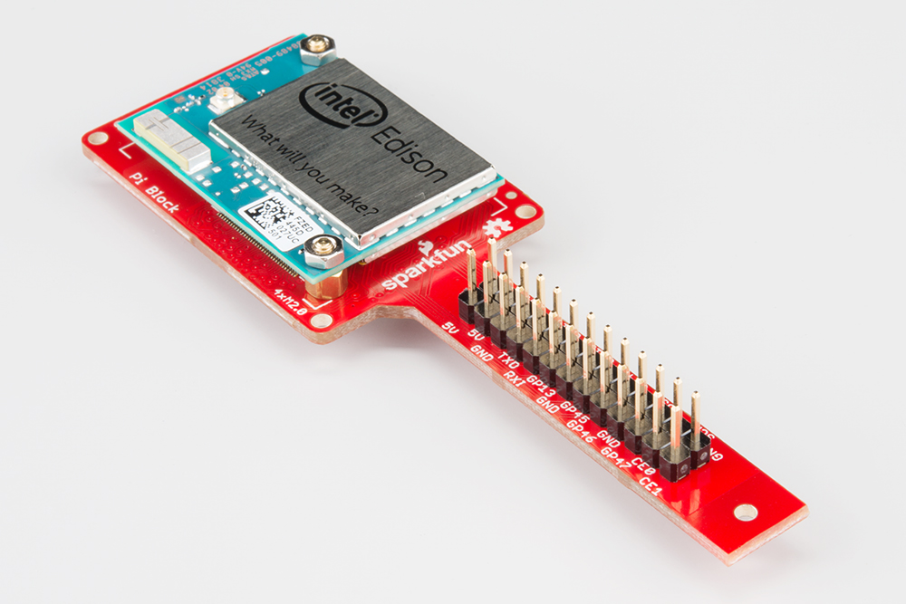
Alternatively, you can populate the back side of the Pi Block with headers. This method gives the same pinout as a Raspberry Pi Model B. You could, in theory, swap the Edison in for your Raspberry Pi on an existing project, or use Raspberry Pi accessories (e.g. Pi Wedge).
Using the Pi Block as an output device
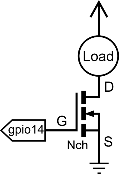
If you want to use the Pi Block to control high power LEDs or relays, an external transistor or MOSFET will be required. It is possible to illuminate a small LED directly from the level shifter. It may not be as bright since the current output of the TXB0108 level converter is very low (~5ma).
In the terminal, we will demonstrate how to activate and use a GPIO pin as an output.
First navigate to the GPIO directory on the Edison.
cd /sys/class/gpio
Select the GPIO pin to enable. In this case, we used GPIO 14, which is labeled "GP14" on the Pi Block.
echo 14 > export
Navigate to the newly created GPIO directory.
cd gpio14
If you type "ls", you should see a bunch of variables.
active_low  direction   power       uevent
device      edge        subsystem   value
Let's set the "direction" of the port to output
echo out > direction
To confirm this, we will "cat" the value
cat direction
You should see the "out" in the command line. Now the device is configured as an output. "value" is where the status of the pin is set, 1 for high, 0 for low.
echo 1 > value
Testing with a multi-meter, small led, or oscilloscope, you should see a "high" status (3.3V) present on gpio14.
Using the Pi Block as an input device
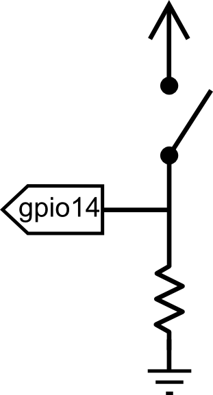
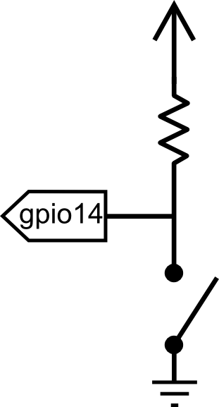
If you want the Pi Block to read switches, buttons, or other logic level inputs, you must pay attention to pull-up and pull-down resistors. The level converter on board is very weak. Here are two scenarios explained:
In the terminal, we will demonstrate how to activate and use a GPIO pin as an input configured as an active high.
First, navigate to the GPIO directory on the Edison.
cd /sys/class/gpio
Select the GPIO pin to enable. In this case let us use GPIO 14.
echo 14 > export
Navigate to the newly created GPIO directory.
cd gpio14
If you type "ls", you should see a bunch of variables.
active_low  direction   power       uevent
device      edge        subsystem   value
Let's set the "direction" of the port to output.
echo in > direction
To confirm this, we will "cat" the value.
cat direction
You should see the "in" in the command line. Now the device is configured as an input. "value" is where the status of the pin is set, 1 for high, 0 for low.
cat value
With a button pressed, you should see a 1. When the button is not pressed you should see a 0. Using the up arrow, you can recall previously run commands.