SparkFun Environmental Sensor Breakout - BME68x (Qwiic) Hookup Guide
 El Duderino, santaimpersonator
Hardware Assembly
- In order to avoid contamination of its gas scanning capabilities, DO NOT touch the metallic casing of the BME688 sensor.
- At first sensor usage, minimum 48 hours of "burn in" should be made. Later, at each usage, 30 min. of functioning should passed before sensor data may be considered as valid.
- To "burn in" the sensor, users just need to power the sensor for 48 hrs.
Using the Qwiic system, assembling the hardware is simple. All you need to do is connect your Environmental Sensor - BME68x (Qwiic) to your chosen development board with a Qwiic cable or adapter cable. Otherwise, you can use the I2C pins broken out if you do not have a Qwiic connector on your development board or if you do not want to use a Qwiic connection. If you are not using a Qwiic-enabled board, make sure your input voltage and logic are either running at 3.3V or you are shifting the logic level from whatever logic your controller runs at to 3.3V for the BME680.
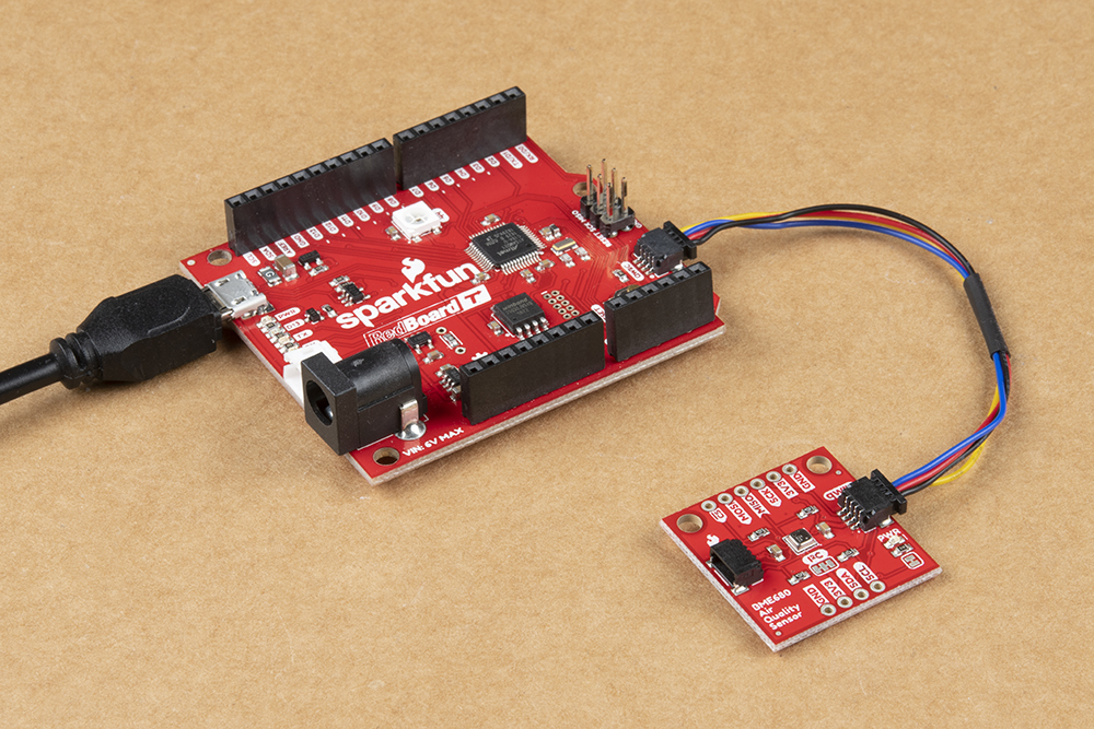
If you would prefer to communicate with the BME680 via SPI, you will need to connect to the SPI pins broken out on this board and route them to the respective pins for SPI communication on your development board (CIPO, COPI, SCK and CS). Also note that this breakout defaults to I2C mode so your code will need to toggle the CS pin LOW once on power up to enable SPI mode. The BME680 will remain in SPI mode until the next power cycle. The SPI examples further on in this guide do that automatically so it's only necessary to note for writing your own code.
ADR and CSB jumpers to enable SPI communication. (*See the Hardware Overview section for more information.)Soldering to the pins is the best option for a secure connection but you can also create temporary connections to those pins for prototyping using something like these IC Hooks. If you are not familiar with through-hole soldering, take a look at this tutorial:
How to Solder: Through-Hole Soldering
September 19, 2013
With everything connected properly, we're ready to move on to uploading a sketch and start monitoring your environment!