SparkFun GPS Dead Reckoning NEO-M8U Hookup Guide
 bboyho,
  Elias The Sparkiest
Hardware Assembly
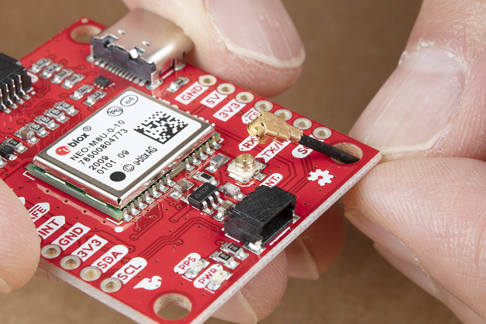
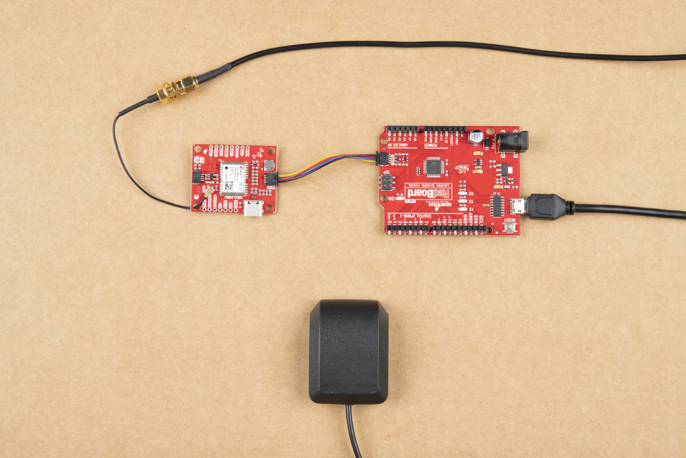
For this example, I used a RedBoard Qwiic and associated USB cable. Connecting the boards with Qwiic cable, the assembly is very simple. Plug a Qwiic cable between the RedBoard and SparkFun NEO-M9U. Then plugged in one of our patch antennas to the u.FL connector. If you need tips on plugging in the U.FL connector, then check out our U.FL tutorial. If you're going to be soldering to the through hole pins for I2C functionality, then just attach lines to power, ground, and the I2C data lines to a microcontroller of your choice. Your setup should look similar to the image below.

For secure connections, you may want to thread the U.FL cable through a mounting hole before connecting. Adding tape or some hot glue will provide some strain relief to prevent the cable from disconnecting.
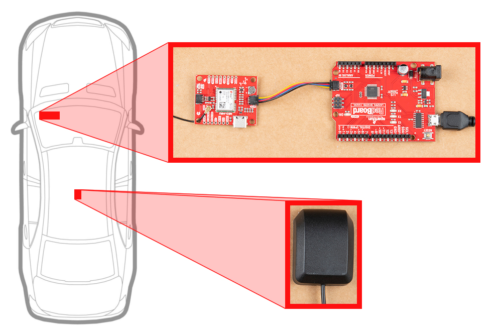
When using the NEO-M8U, you will want to orient the board according to the guidelines explained earlier. Below is a top-down view with the board pointing down.
Make sure to secure the board above a vehicle's dashboard using some tape or sticky tack when prototyping and testing. For best signal reception, it is suggested to guide the antenna from the inside of the car and through a window before attaching the GPS on top of a car.