SparkFun Inventor's Kit Experiment Guide - v4.0
 Joel_E_B
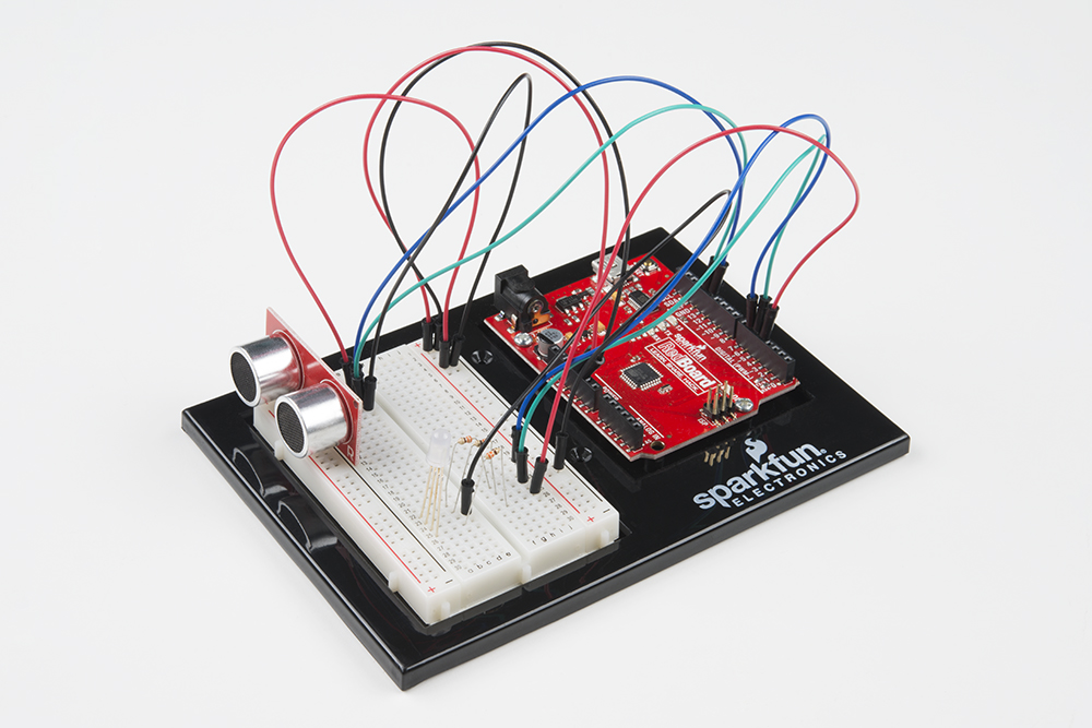
Circuit 3B: Distance Sensor
Distance sensors are amazing tools with all kinds of uses. They can sense the presence of an object, they can be used in experiments to calculate speed and acceleration, and they can be used in robotics to avoid obstacles. This circuit will walk you through the basics of using an ultrasonic distance sensor, which measures distance using sound waves!
Parts Needed
Grab the following quantities of each part listed to build this circuit:

New Components
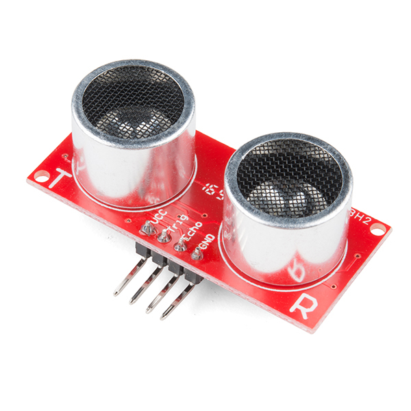
Ultrasonic Distance Sensor
Distance sensors work by sending pulses of light or sound out from a transmitter, then timing how long it takes for the signals to bounce off an object and return to a receiver (just like sonar). Some sensors use infrared light, some use lasers, and some, like the HC-SR04 included in your kit, use ultrasonic sound (sound so high-pitched that you can’t hear it).
New Concepts
Datasheets
When working with electronics, datasheets are your best friend. Datasheets contain all the relevant information needed to get you up and running with a part. In this circuit, we are calculating distance based on the time it takes sound waves to be transmitted, bounce off an object and then be received. But, how can we tell distance from that information? The answer lies in the datasheet for the distance sensor. In it, you can find the equation the program needs to interpret distance from the time it takes the sound wave to travel.
Else If Statement
In the night-light circuit, you used an if/else statement to run one set of code when a logic statement was true, and a different set of code when it was false. What if you wanted to have more than two options? Else if statements let you run as many logical tests as you want in one if statement. For example, in the code for this circuit, there is an if statement that flows like this:
- If the distance is less than 10, make the RGB LED red.
- Else if the distance is more than 10 but less than 20, make the RGB LED yellow.
- Else make the RGB LED green.
If you wanted to have four or five colors for different distances, you could add more else if statements.
Else if statements are different from nested if statements in that only one of the statements above can be true, whereas you could have multiple nested if statements that could true.
Hardware Hookup
| Polarized Components | Pay special attention to the component’s markings indicating how to place it on the breadboard. Polarized components can only be connected to a circuit in one direction. |
The distance sensor is polarized. Take note of the pin labels when connecting your circuit.
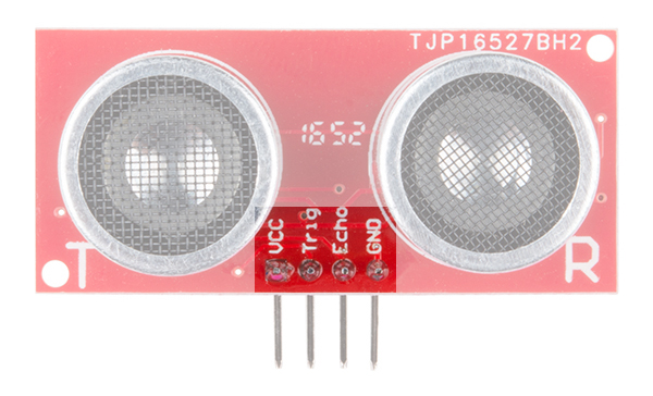
The following table describes the function of each pin on the distance sensor:
| Pin | Description |
|---|---|
| VCC | Power (5V) |
| Trig | Trigger Pulse Input: Sends bursts of ultrasound at 40kHz. |
| Echo | Echo Pulse Output: Receives echo signal. Range is calculated by the proportion of trigger signal sent and echo signal received. |
| GND | Ground (0V) |
Ready to start hooking everything up? Check out the Fritzing diagram below to see how everything is connected.
Circuit Diagram
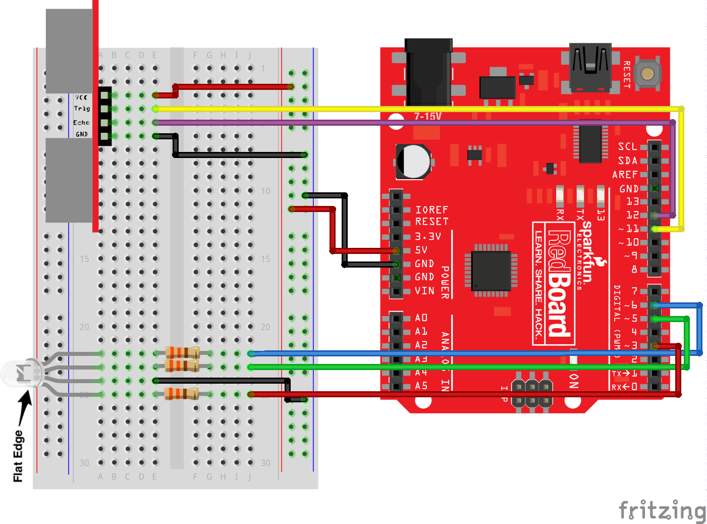
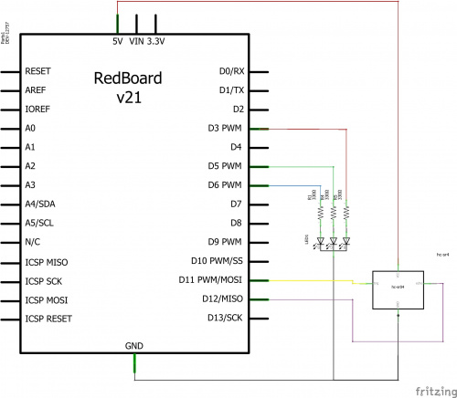
Having a hard time seeing the circuit? Click on the image for a closer look.
Hookup Table
| Component | RedBoard | Breadboard | Breadboard | Breadboard | Breadboard |
|---|---|---|---|---|---|
| Jumper Wire | 5V | 5V Rail ( + ) | |||
| Jumper Wire | GND | GND Rail ( - ) | |||
| RGB LED | A25 (RED) | A24 (GND) | A23 (GREEN) | A22 (BLUE) | |
| 330Ω Resistor (orange, orange, brown) |
E22 | F22 | |||
| 330Ω Resistor (orange, orange, brown) |
E23 | F23 | |||
| 330Ω Resistor (orange, orange, brown) |
E25 | F25 | |||
| Jumper Wire | E24 | GND Rail ( - ) | |||
| Jumper Wire | Digital Pin 3 | J25 | |||
| Jumper Wire | Digital Pin 5 | J23 | |||
| Jumper Wire | Digital Pin 6 | J22 | |||
| Distance Sensor | A3 (Vcc) | A4 (Trig) | A5 (Echo) | A6 (GND) | |
| Jumper Wire | Digital Pin 11 | E4 (Trig) | |||
| Jumper Wire | Digital Pin 12 | E5 (Echo) | |||
| Jumper Wire | E3 | 5V Rail ( + ) | |||
| Jumper Wire | E6 | GND Rail ( - ) |
Open the Sketch
To open the code, go to: File > Examples > SIK_Guide_Code-V_4 > SIK_Circuit_3B-DistanceSensor
You can also copy and paste the following code into the Arduino IDE. Hit upload, and see what happens!
language:cpp
/*
  SparkFun Inventor’s Kit
  Circuit 3B-Distance Sensor

  Control the color of an RGB LED using an ultrasonic distance sensor.

  This sketch was written by SparkFun Electronics, with lots of help from the Arduino community.
  This code is completely free for any use.

  View circuit diagram and instructions at: https://learn.sparkfun.com/tutorials/sparkfun-inventors-kit-experiment-guide---v40
  Download drawings and code at: https://github.com/sparkfun/SIK-Guide-Code
*/

const int trigPin = 11;           //connects to the trigger pin on the distance sensor
const int echoPin = 12;           //connects to the echo pin on the distance sensor

const int redPin = 3;             //pin to control the red LED inside the RGB LED
const int greenPin = 5;           //pin to control the green LED inside the RGB LED
const int bluePin = 6;            //pin to control the blue LED inside the RGB LED

float distance = 0;               //stores the distance measured by the distance sensor

void setup()
{
  Serial.begin (9600);        //set up a serial connection with the computer

  pinMode(trigPin, OUTPUT);   //the trigger pin will output pulses of electricity
  pinMode(echoPin, INPUT);    //the echo pin will measure the duration of pulses coming back from the distance sensor

  //set the RGB LED pins to output
  pinMode(redPin, OUTPUT);
  pinMode(greenPin, OUTPUT);
  pinMode(bluePin, OUTPUT);
}

void loop() {
  distance = getDistance();   //variable to store the distance measured by the sensor

  Serial.print(distance);     //print the distance that was measured
  Serial.println(" in");      //print units after the distance

  if (distance <= 10) {                       //if the object is close

    //make the RGB LED red
    analogWrite(redPin, 255);
    analogWrite(greenPin, 0);
    analogWrite(bluePin, 0);

  } else if (10 < distance && distance < 20) { //if the object is a medium distance

    //make the RGB LED yellow
    analogWrite(redPin, 255);
    analogWrite(greenPin, 50);
    analogWrite(bluePin, 0);

  } else {                                    //if the object is far away

    //make the RGB LED green
    analogWrite(redPin, 0);
    analogWrite(greenPin, 255);
    analogWrite(bluePin, 0);
  }

  delay(50);      //delay 50ms between each reading
}

//------------------FUNCTIONS-------------------------------

//RETURNS THE DISTANCE MEASURED BY THE HC-SR04 DISTANCE SENSOR
float getDistance()
{
  float echoTime;                   //variable to store the time it takes for a ping to bounce off an object
  float calculatedDistance;         //variable to store the distance calculated from the echo time

  //send out an ultrasonic pulse that's 10ms long
  digitalWrite(trigPin, HIGH);
  delayMicroseconds(10);
  digitalWrite(trigPin, LOW);

  echoTime = pulseIn(echoPin, HIGH);      //use the pulsein command to see how long it takes for the
                                          //pulse to bounce back to the sensor

  calculatedDistance = echoTime / 148.0;  //calculate the distance of the object that reflected the pulse (half the bounce time multiplied by the speed of sound)

  return calculatedDistance;              //send back the distance that was calculated
}
What You Should See
Move your hand or a large, flat object closer and farther away from the distance sensor. As the object approaches, the light will change from green to yellow to red.
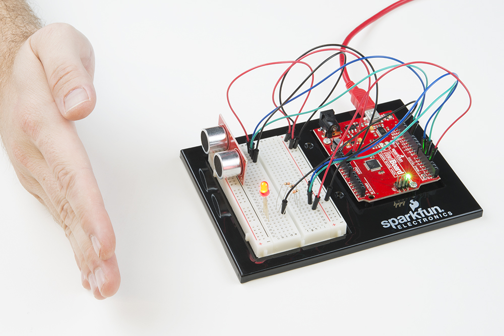
Open the Serial Monitor, and you should see the distance printed to the window.
Program Overview
- Check what distance the sensor is reading. a. If the distance is less than 10 inches, make the RGB LED red. b. If the distance is between 10 and 20 inches, make the RGB LED yellow. c. If the distance value is not equal to the fist two conditions, make the RGB LED green.
Code to Note
| Code | Description |
|---|---|
Float Variables:float echoTime; |
The float variable, short for floating-point number, is similar to an integer except it can represent numbers that contain a decimal point. Floats are good for representing values that need to be more precise than an int. Floats allow us to measure precise distances such as 9.33 inches instead of just 9 inches. |
Else if Statement:if(logic statement){else(default logic statement){ |
Else if statements let you combine more than one logic statement. Arduino will test each logic statement in order; if one is true it will run the code in that section and then skip all of the other sections of code in the if statement. |
User-Defined Function:getDistance(); |
This function tells the distance sensor to send out an ultrasonic wave form, measures the time it takes to bounce back to the sensor, then calculates the distance based on the speed of sound. This calculation is based off information found in the distance sensor's datasheet. |
Coding Challenges
| Challenge | Description |
|---|---|
| Change the limits of the distance sensor | Try editing the values in the logic statements so that the RGB LED changes color at different distances. |
| Change the units of the distance sensor | Try editing the code so that the distance sensor outputs a different unit of length, such as centimeters or feet. |
| Add a fourth color | Try adding another else if statement so that there are four different colors instead of three. |
Troubleshooting
| Problem | Solution |
|---|---|
| The RGB LED colors aren't working or a color is missing | Check the connection for the wire and resistor connected to each leg of the LED. Ensure the RGB LED is inserted in the correct orientation. |
| The distance sensor doesn’t seem to work | Open up the serial monitor on your computer. You should see a stream of distances being printed in the monitor. If they are all reading 0 or jump around, then check the wiring on your sensor. |
| The distance sensor still doesn’t work | Ultrasonic noise pollution will interfere with your distance sensor readings. If you aim two distance sensors at each other, they will confuse each other. Some air-conditioning systems may also emit noises in the ultrasonic range. Try pointing your sensor away from the other distance sensors or changing to a different location. |