SparkFun Inventor's Kit Experiment Guide - v4.0
 Joel_E_B
Circuit 3C: Motion Alarm
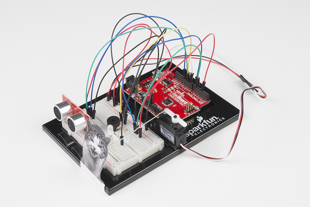
Time to take your distance sensor project to the next level. Let’s imagine that you want to stop your cat from prowling around your countertop. This circuit will use light, sound and motion to scare away your cat when it is detected by the distance sensor. Using a servo motor, you can add a moving pop-up to animate your alarm.
Don’t have a cat? No problem! This circuit can be adapted for a variety of projects such as a room alarm, an automated pop-up story, an automatic treat dispenser and so much more. Let your imagination run wild with this project.
Parts Needed
Grab the following quantities of each part listed to build this circuit:
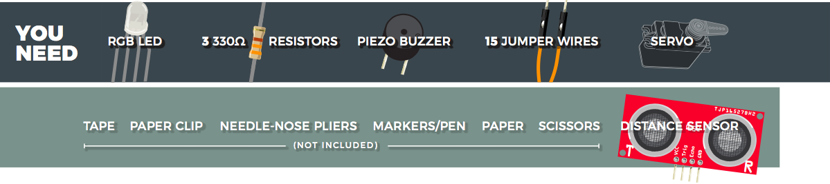
Additional Materials (NOT INCLUDED)
The following materials are optional. The circuit can be completed without these items.
- Paper
- Scissors
- Scotch™ Tape
- Markers/Pen
- Paper Clip
- Needle-Nose Pliers
New Concepts
Getting Creative With Mechanisms
This circuit gets really fun when you start to use your servo to animate the world around you. To do this, you’ll need to connect your servo to some physical mechanisms. Tape and hot glue are easy ways to connect things to your servo. You can also loop a paper clip through the small holes in the servo arm to serve as a linkage. See the Hardware Hookup section below for more information.

Hardware Hookup
If you have opted for the extra materials, use the following instructions to create the moving pop-up for your cat alarm.
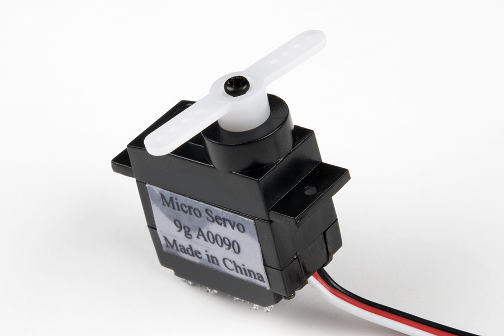
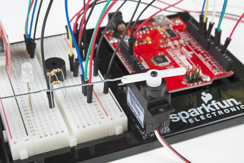
To begin, attach your servo to the baseplate using Dual Lock, as described in Circuit 3A.
Attach the servo mount of your choice. It is recommended you wait until after you have uploaded your code to ensure the mount is in the best position before screwing on the mount. The screw is optional, but it will make for a more robust mechanism.
Next, use needle-nose pliers to bend the paper clip straight. Imagine a 3D space. The straight clip is the X-axis. Bend one end of the paper clip 90 degrees along the Y-axis. The bent segment should be about 1 inch or 2.5cm long. Then bend the other end along the Z-axis. This bend should be about 1/8 inch or 3mm long. Repeat this bend once more back toward the X-axis, making a hook shape. You should now have a linkage rod that looks something like this:
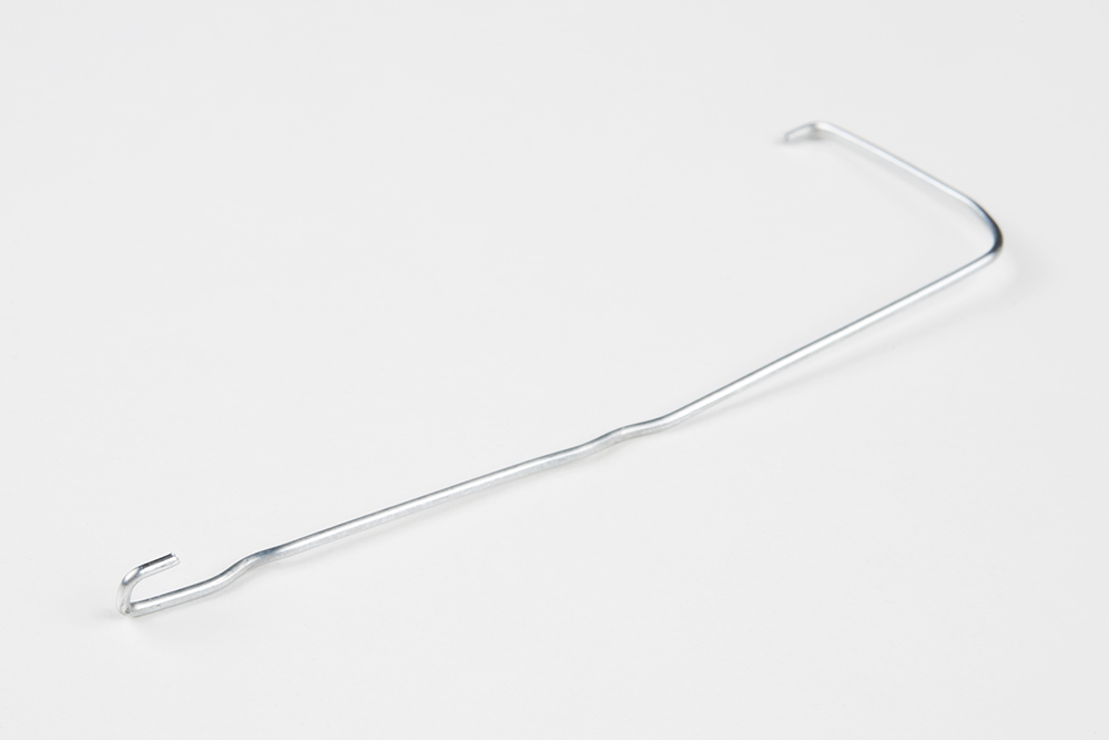
Attach the hook end of the linkage rod to the end hole on your servo mount.
Cut out the pop-up image of your choice. We chose this public domain menacing cat image (http://bit.ly/2vinyE1). The image you choose should be about 2.5 inches x 2.5 inches and can be drawn or printed. Leave a rectangular strip of paper under the image that is about 2 inches long. Fold along the bottom of the image. Tape the pop-up to the underside of the breadbaord baseplate on the same side to which the servo is connected.
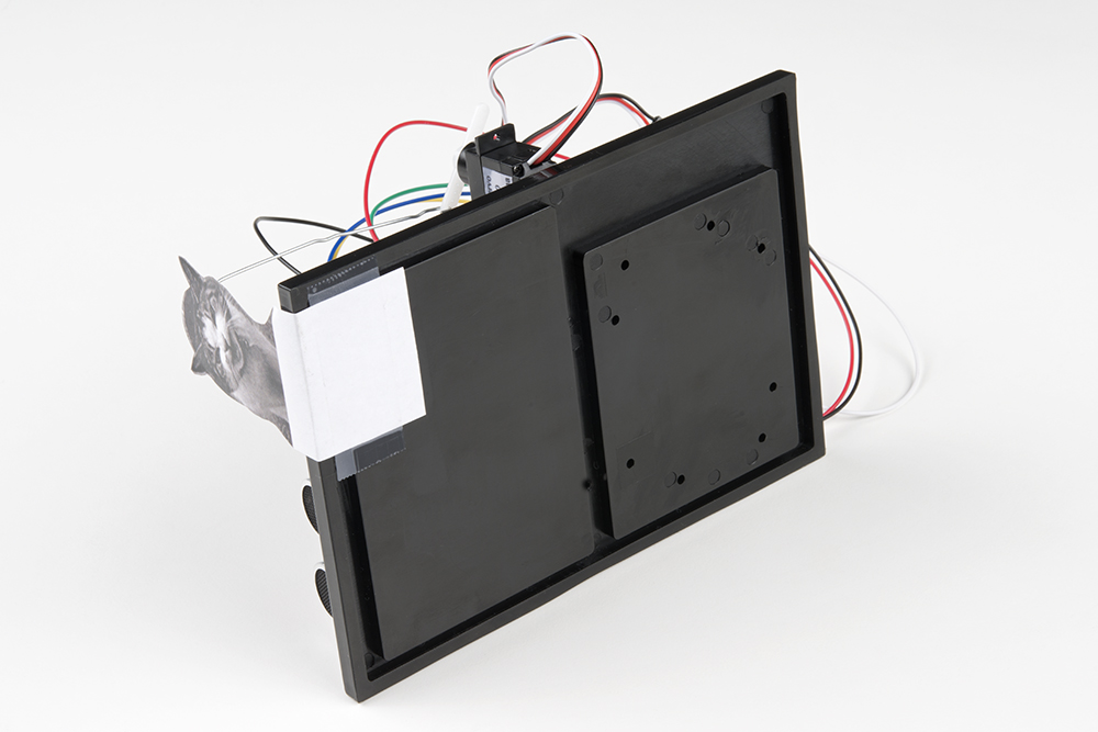
Last, tape the free end of the rod to the back of your pop-up image.

Once you have the rest of the circuit built and the code uploaded, you can fine-tune your moving pop-up and make any necessary adjustments. Remember to wait until these adjustments have been made before you screw the servo mount onto the motor.
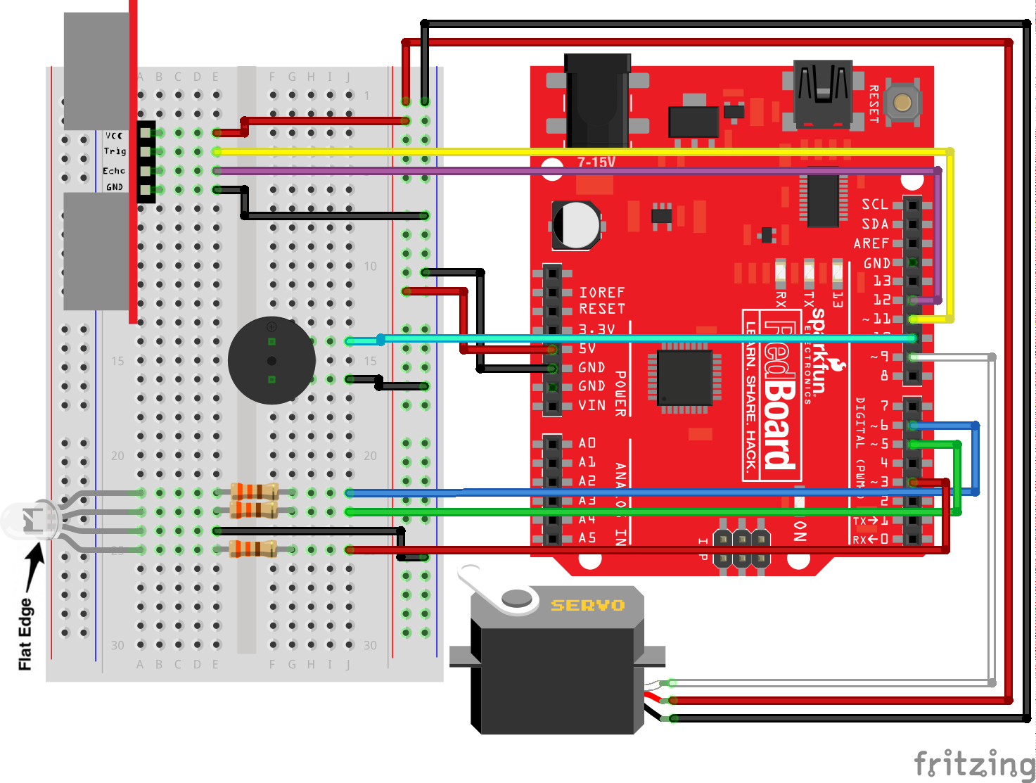
Ready to start hooking everything up? Check out the Fritzing diagram below to see how everything is connected.
Circuit Diagram
Hookup Table
| Component | RedBoard | Breadboard | Breadboard | Breadboard | Breadboard | Servo |
|---|---|---|---|---|---|---|
| Jumper Wire | 5V | 5V Rail ( + ) | ||||
| Jumper Wire | GND | GND Rail ( - ) |
||||
| RGB LED | A25 (RED) | A24 (GND) | A23 (GREEN) | A22 (BLUE) | ||
| 330Ω Resistor (orange, orange, brown) |
E22 | F22 | ||||
| 330Ω Resistor (orange, orange, brown) |
E23 | F23 | ||||
| 330Ω Resistor (orange, orange, brown) |
E25 | F25 | ||||
| Jumper Wire | E24 | GND Rail ( - ) |
||||
| Jumper Wire | Digital Pin 3 | J25 | ||||
| Jumper Wire | Digital Pin 5 | J23 | ||||
| Jumper Wire | Digital Pin 6 | J22 | ||||
| Distance Sensor | A3 (Vcc) | A4 (Trig) | A5 (Echo) | A6 (GND) | ||
| Jumper Wire | Digital Pin 11 | E4 (Trig) | ||||
| Jumper Wire | Digital Pin 12 | E5 (Echo) | ||||
| Jumper Wire | E3 | 5V Rail ( + ) | ||||
| Jumper Wire | E6 | GND Rail ( - ) |
||||
| Buzzer | F14 (Buzzer +) |
F16 (Buzzer -) |
||||
| Jumper Wire | Digital Pin 10 | J14 | ||||
| Jumper Wire | J16 | GND Rail ( - ) |
||||
| Jumper Wire | Digital Pin 9 | White Servo Pin | ||||
| Jumper Wire | 5V Rail ( + ) | Red Servo Pin | ||||
| Jumper Wire | GND Rail ( - ) |
Black Servo Pin |
Open the Sketch
To open the code, go to: File > Examples > SIK_Guide_Code-V_4 > SIK_Circuit_3C-CatAlarm
You can also copy and paste the following code into the Arduino IDE. Hit upload, and see what happens!
language:cpp
/*
  SparkFun Inventor’s Kit
  Circuit 3C-Motion Alarm

  Control the color of an RGB LED using an ultrasonic distance sensor. When an object is close to the sensor, buzz the buzzer and wiggle the servo motor.

  This sketch was written by SparkFun Electronics, with lots of help from the Arduino community.
  This code is completely free for any use.

  View circuit diagram and instructions at: https://learn.sparkfun.com/tutorials/sparkfun-inventors-kit-experiment-guide---v40
  Download drawings and code at: https://github.com/sparkfun/SIK-Guide-Code
*/

#include <Servo.h>                //include the servo library

const int trigPin = 11;           //connects to the trigger pin on the distance sensor
const int echoPin = 12;           //connects to the echo pin on the distance sensor

const int redPin = 3;             //pin to control the red LED inside the RGB LED
const int greenPin = 5;           //pin to control the green LED inside the RGB LED
const int bluePin = 6;            //pin to control the blue LED inside the RGB LED

const int buzzerPin = 10;         //pin that will drive the buzzer

float distance = 0;               //stores the distance measured by the distance sensor

Servo myservo;                    //create a servo object

void setup()
{
  Serial.begin (9600);        //set up a serial connection with the computer

  pinMode(trigPin, OUTPUT);   //the trigger pin will output pulses of electricity
  pinMode(echoPin, INPUT);    //the echo pin will measure the duration of pulses coming back from the distance sensor

  //set the RGB LED pins to output
  pinMode(redPin, OUTPUT);
  pinMode(greenPin, OUTPUT);
  pinMode(bluePin, OUTPUT);

  pinMode(buzzerPin, OUTPUT);   //set the buzzer pin to output

  myservo.attach(9);            //use pin 9 to control the servo

}

void loop() {
  distance = getDistance();   //variable to store the distance measured by the sensor

  Serial.print(distance);     //print the distance that was measured
  Serial.println(" in");      //print units after the distance

  if (distance <= 10) {                       //if the object is close

    //make the RGB LED red
    analogWrite(redPin, 255);
    analogWrite(greenPin, 0);
    analogWrite(bluePin, 0);

    //this code wiggles the servo and beeps the buzzer
    tone(buzzerPin, 272);         //buzz the buzzer pin
    myservo.write(10);            //move the servo to 45 degrees
    delay(100);                   //wait 100 milliseconds

    noTone(buzzerPin);            //turn the buzzer off
    myservo.write(150);           //move the servo to 135 degrees
    delay(100);                   //wait 100 milliseconds


  } else if (10 < distance && distance < 20) { //if the object is a medium distance

    //make the RGB LED yellow
    analogWrite(redPin, 255);
    analogWrite(greenPin, 50);
    analogWrite(bluePin, 0);

  } else {                                    //if the object is far away

    //make the RGB LED green
    analogWrite(redPin, 0);
    analogWrite(greenPin, 255);
    analogWrite(bluePin, 0);
  }

  delay(50);      //delay 50ms between each reading
}

//------------------FUNCTIONS-------------------------------

//RETURNS THE DISTANCE MEASURED BY THE HC-SR04 DISTANCE SENSOR
float getDistance()
{
  float echoTime;                   //variable to store the time it takes for a ping to bounce off an object
  float calculatedDistance;         //variable to store the distance calculated from the echo time

  //send out an ultrasonic pulse that's 10ms long
  digitalWrite(trigPin, HIGH);
  delayMicroseconds(10);
  digitalWrite(trigPin, LOW);

  echoTime = pulseIn(echoPin, HIGH);      //use the pulsein command to see how long it takes for the
                                          //pulse to bounce back to the sensor

  calculatedDistance = echoTime / 148.0;  //calculate the distance of the object that reflected the pulse (half the bounce time multiplied by the speed of sound)

  return calculatedDistance;              //send back the distance that was calculated
}
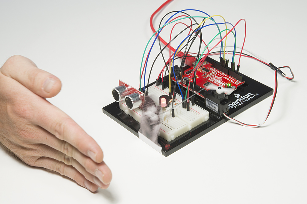
What You Should See
The RGB LED will behave as in your last circuit. It will be green when objects are far, yellow when they are midrange and red when they are close. When an object is close the buzzer will also beep, and the servo will rotate back and forth.
Program Overview
- Check what distance the sensor is reading. a. If the distance is less than 10 inches, make the RGB LED red. Then make the servo rotate back and forth and make the buzzer beep. b. If the distance is between 10 and 20 inches, make the RGB LED yellow. c. If the distance value is not equal to the fist two conditions, make the RGB LED green.
Code to Note
| Code | Description |
|---|---|
Constants: const int trigPin = 11; |
Constants are variables that have been marked as "read-only" and cannot have their value changed as the program progresses. Constants are great for declaring pin number variables that will not change throughout the program. |
No Tone Function: |
In circuit 2A you made songs using a buzzer and the tone function, but you gave the tone function three parameters: a pin number, a frequency and a duration. You can leave out the third parameter, and the tone will play until you change it or turn it off. noTone() turns off a pin that has been activated with the tone command.
|
Coding Challenges
| Challenge | Description |
|---|---|
| Change the servo behavior | Try changing the way that your servo behaves when the distance sensor is triggered. |
| Change the alarm settings | Try altering the code so the alarm goes off from much farther or closer distances. |
| Create a different mechanism | Try your hand at making different objects move with your servo motor. Make an interactive pop-up story. Make an automatic fish feeder. Time to use your imagination! |
Troubleshooting
| Problem | Solution |
|---|---|
| The RGB LED colors aren't working or a color is missing | Check the connection for the wire and resistor connected to each leg of the LED. Ensure the RGB LED is inserted in the correct orientation. |
| The distance sensor doesn’t seem to work | Open up the Serial Monitor on your computer. You should see a stream of distances being printed in the monitor. If they are all reading 0 or jumping around, then check the wiring on your sensor. |
| The distance sensor still doesn’t work | Ultrasonic noise pollution will interfere with your distance sensor readings. If you aim two distance sensors at each other, they will confuse each other. Some air conditioning systems may also emit noises in the ultrasonic range. Try pointing your sensor away from the other distance sensors or changing to a different location. |
| The servo doesn’t work | Make sure all of your servo wires are connected. Be sure that the black wire is connected to the negative rail and the red wire is connected to the positive rail. Make sure you are using a digital pin that is capable of PWM. |
| The pop-up is moving too much or not enough | The two lines of code that pass angles to the servo motor are myservo.write(45); and myservo.write(135);. Try changing these angle values to fine-tune your mechanism. |