SparkFun Inventor's Kit Experiment Guide - v4.1
 Joel_E_B,
  bboyho
Circuit 4A: LCD "Hello, World!"
Printing “Hello, world!” is usually the first thing that programming tutorials will have you do in a new language. This guide starts by blinking an LED, but now we’re going to print out real text using a Liquid Crystal Display (LCD).
Parts Needed
Grab the following quantities of each part listed to build this circuit:

New Components
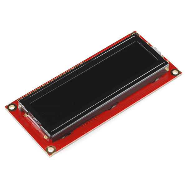
Character Liquid Crystal Display (LCD)
Character LCDs are designed to show a grid of letters, numbers and a few special characters. This makes them great for printing data and showing values. When current is applied to this special kind of crystal, it turns opaque. This is used in a lot of calculators, watches and simple displays. Adding an LCD to your project will make it super portable and allow you to integrate up to 32 characters (16 x 2) of information.
New Concepts
Contrast
Pin 3 on the LCD controls the contrast and brightness of the LCD. Using a simple voltage divider with a potentiometer, the contrast can be adjusted. As you rotate the knob on the potentiometer, you should notice that the screen will get brighter or darker and that the characters become more visible or less visible. The contrast of LCDs is highly dependent on factors such as temperature and the voltage used to power it. Thus, external contrast knobs are needed for displays that cannot automatically account for temperature and voltage changes.
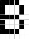
Pixels
If you look closely at the characters on the LCD, you will notice that they are actually made up of lots of little squares. These little squares are called pixels. The size of displays is often represented in pixels. Pixels make up character space, which is the number of pixels in which a character can exist.
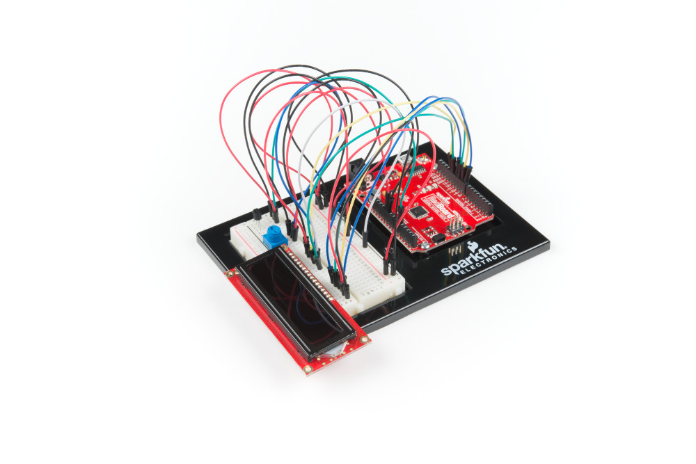
Hardware Hookup
| Polarized Components | Pay special attention to the component’s markings indicating how to place it on the breadboard. Polarized components can only be connected to a circuit in one direction. |
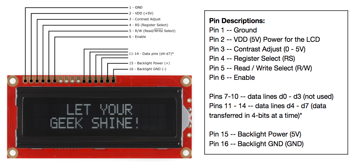
The LCD has 16 pins, and it is polarized. The pins are numbered from left to right, 1 through 16. The LCD utilizes an extremely common parallel interface LCD driver chip from Hitachi called the HD44780. Thankfully, the Arduino community has developed a library to handle a great deal of the software-to-hardware interface. Below is a list of each of the pins on the LCD.
Ready to start hooking everything up? Check out the circuit diagram and hookup table below to see how everything is connected.
Circuit Diagram
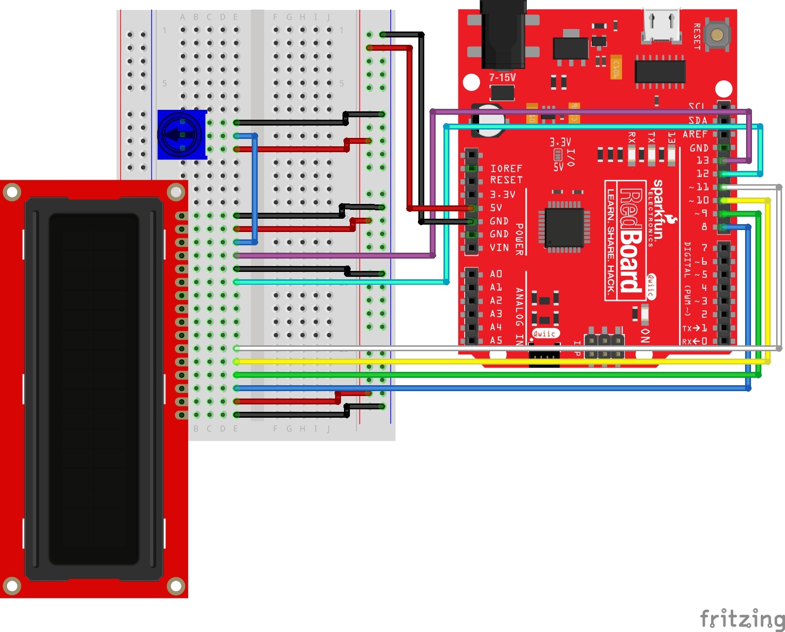
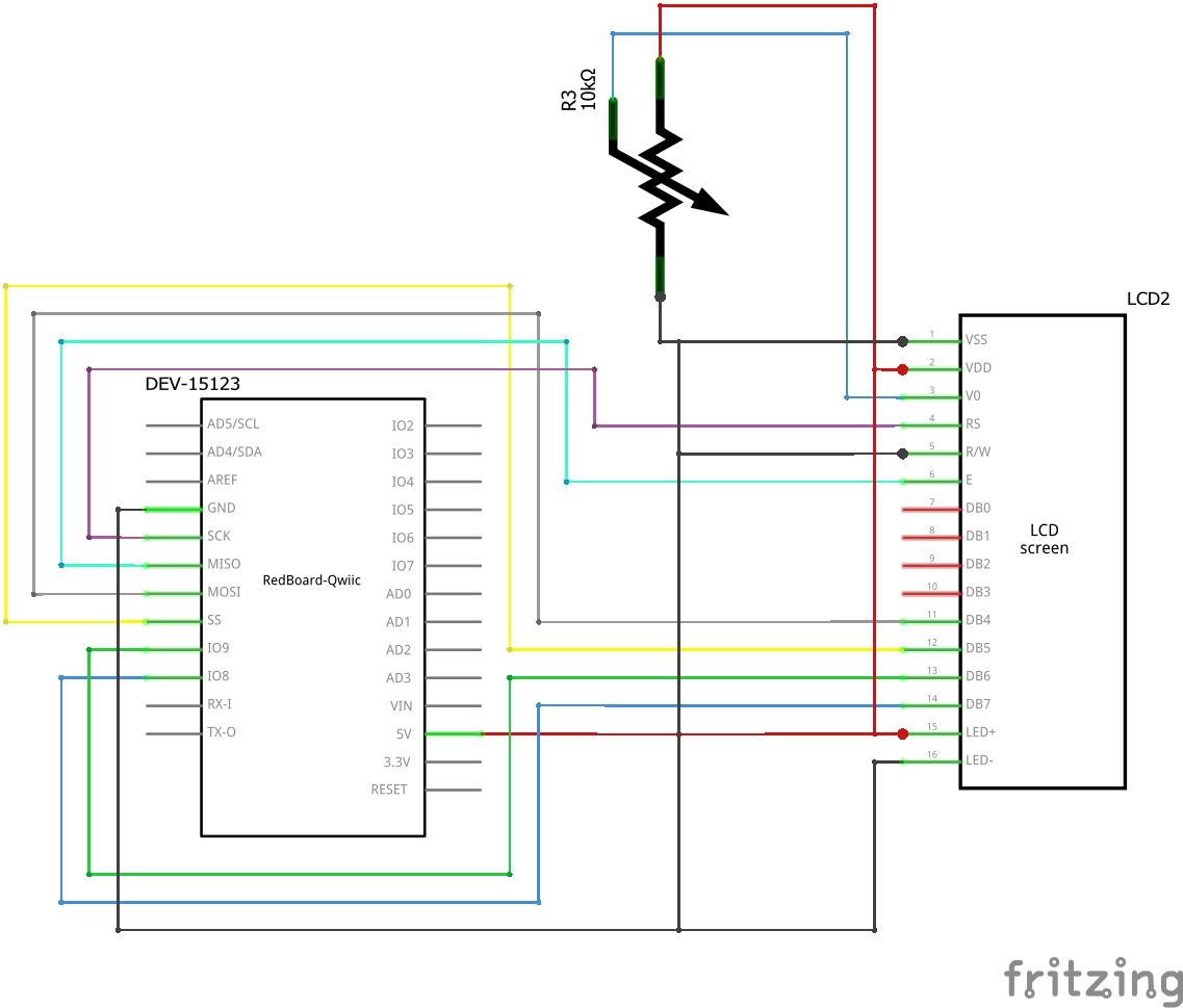
Having a hard time seeing the circuit? Click on the image for a closer look.
Hookup Table
| Component | RedBoard | Breadboard | Breadboard | Breadboard |
|---|---|---|---|---|
| Jumper Wire | 5V | 5V Rail ( + ) | ||
| Jumper Wire | GND | GND Rail ( - ) | ||
| LCD | A15-A30 (Pin 1 on A15) | |||
| Jumper Wire | E30 | GND Rail ( - ) | ||
| Jumper Wire | E29 | 5V Rail ( + ) | ||
| Jumper Wire | Digital Pin 8 | E28 | ||
| Jumper Wire | Digital Pin 9 | E27 | ||
| Jumper Wire | Digital Pin 10 | E26 | ||
| Jumper Wire | Digital Pin 11 | E25 | ||
| Jumper Wire | Digital Pin 12 | E20 | ||
| Jumper Wire | E19 | GND Rail ( - ) | ||
| Jumper Wire | Digital Pin 13 | E18 | ||
| Jumper Wire | E16 | 5V Rail ( + ) | ||
| Jumper Wire | E15 | GND Rail ( - ) | ||
| Potentiometer | A8 | A9 | A10 | |
| Jumper Wire | E9 | E17 | ||
| Jumper Wire | E8 | GND Rail ( - ) | ||
| Jumper Wire | E10 | 5V Rail ( + ) |
Open the Sketch
To open the code, go to: File > Examples > SIK_Guide_Code-master > SIK_Circuit_4A-LCDHelloWorld
You can also copy and paste the following code into the Arduino IDE. Hit upload, and see what happens!
language:cpp
/*
  SparkFun Inventor’s Kit
  Circuit 4A-HelloWorld

  The LCD will display the words "Hello World" and show how many seconds have passed since
  the RedBoard was last reset.

  This sketch was written by SparkFun Electronics, with lots of help from the Arduino community.
  This code is completely free for any use.

  View circuit diagram and instructions at: https://learn.sparkfun.com/tutorials/sparkfun-inventors-kit-experiment-guide---v41
  Download drawings and code at: https://github.com/sparkfun/SIK-Guide-Code
*/

#include <LiquidCrystal.h>          //the liquid crystal library contains commands for printing to the display

LiquidCrystal lcd(13, 12, 11, 10, 9, 8);   // tell the RedBoard what pins are connected to the display

void setup() {

  lcd.begin(16, 2);                 //tell the lcd library that we are using a display that is 16 characters wide and 2 characters high
  lcd.clear();                      //clear the display
}

void loop() {

  lcd.setCursor(0, 0);              //set the cursor to the 0,0 position (top left corner)
  lcd.print("Hello, world!");       //print hello, world! starting at that position

  lcd.setCursor(0, 1);              //move the cursor to the first space of the bottom row
  lcd.print(millis() / 1000);       //print the number of seconds that have passed since the last reset
}
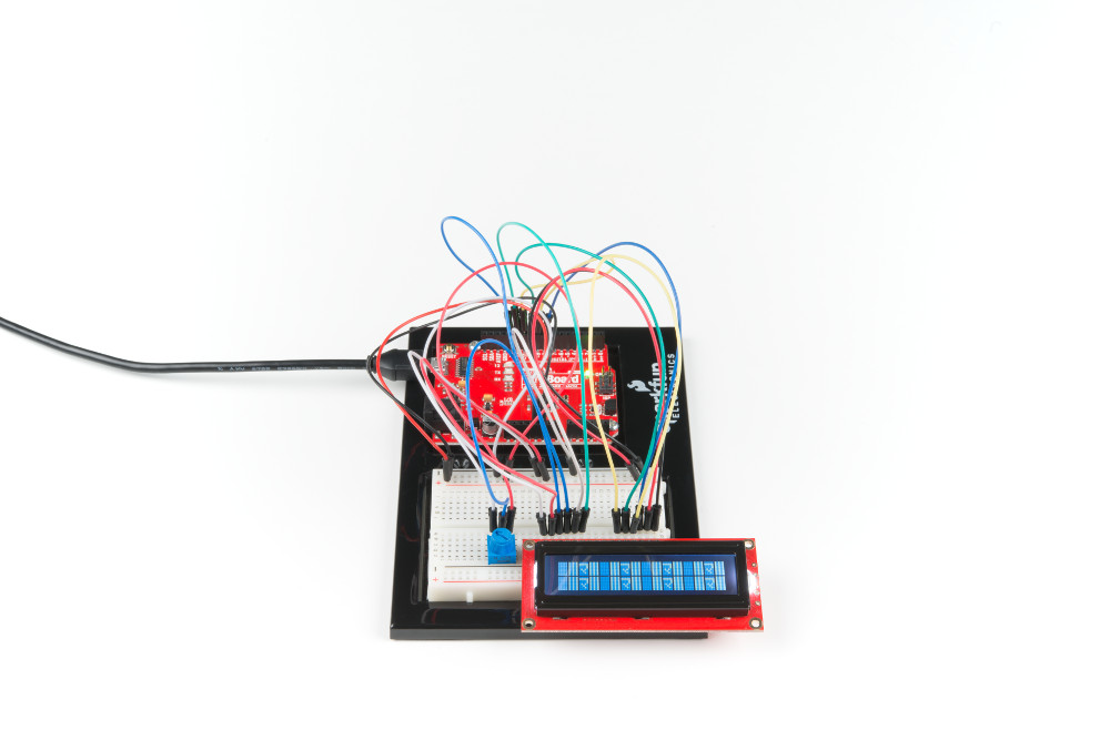
What You Should See
The LCD screen will show “Hello, world!” On the row below, a counter will count every second that passes.

Contrast Adjust
If you are not seeing any characters, are seeing barely visible characters, or see just white rectangles, then you need to adjust the contrast. Twist the potentiometer very slowly until you can clearly read the display. If you reach the end of the potentiometer's rotation, try twisting in the opposite direction.
Program Overview
- Import the LCD library.
- Make an LCD object called “lcd” that will be controlled using pins 8, 9, 10, 11, 12 and 13.
- “Begin” the LCD. This sets the dimensions of the LCD that you are working with (16 x 2). It needs to be called before any other commands from the LCD library are used.
- Clear the display.
- Set the cursor to the top left corner
lcd.setCursor(0,0);, then print “Hello, world!" - Move the cursor to the first space of the lower line
lcd.setCursor(0,1);, then print the number of seconds that have passed since the RedBoard was last reset.
Code to Note
| Code | Description |
|---|---|
LCD Library:#include <LiquidCrystal.h> | Includes the liquid crystal library into your program. |
LCD Library Instance:LiquidCrystal LCD_name(RS_pin, enable_pin, d4, d5, d6, d7); | As with servos, you need to create an LCD object and give it a name (you can make more than one). The numbers in the brackets are pins on the RedBoard that connect to specific pins on the LCD. |
LCD Begin:lcd.begin(16, 2); | This line initializes the LCD object and tells the program the LCD's dimensions. In this case it is 16 characters by 2 characters. |
LCD Clear:lcd.clear(); | This method clears the pixels on the display. |
LCD Cursor:lcd.setCursor(0,0); | Move the cursor to a point on the 16x2 grid of characters. Text that you write to the LCD will start from the cursor. This line is starting back at position (0,0). |
LCD Print :lcd.print("Hello, world!"); | Prints a string of characters to the LCD starting at the cursor position. |
Coding Challenges
| Challenge | Description |
|---|---|
| Change the message | Try changing the code to display another message. |
| Show hours, minutes and seconds | Try adding some code so that the display shows the hours, minutes and seconds that have passed since the RedBoard was last reset. |
| Count button presses | By adding a button to the circuit, you can count the number of times the button was pressed or have the button change what the LCD is displaying. There could be many pages of information. |
Troubleshooting
| Problem | Solution |
|---|---|
| The screen is blank or flickering | Adjust the contrast by twisting the potentiometer. If it’s incorrectly adjusted, you won’t be able to read the text. Also, check the potentiometer, and make sure it's connected correctly. |
| Not working at all | Double check the circuit's wiring. There are a lot of wires in this circuit, and it's easy to mix up one or two. |
| Rectangles in first row | If you see 16 rectangles (like “█”) on the first row, it may be due to the jumper wires being loose on the breadboard. This is normal and can happen with other LCDs wired in parallel with a microcontroller. Make sure that the wires are fully inserted into the breadboard, then try pressing the reset button and adjusting the contrast using the potentiometer. |
| Still not working? | Jumper wires unfortunately can go "bad" from getting bent too much. The copper wire inside can break, leaving an open connection in your circuit. If you are certain that your circuit is wired correctly and that your code is error-free and uploaded but you are still encountering issues, try replacing one or more of the jumper wires for the component that is not working. |