SparkFun Inventor's Kit Experiment Guide - v4.1
 Joel_E_B,
  bboyho
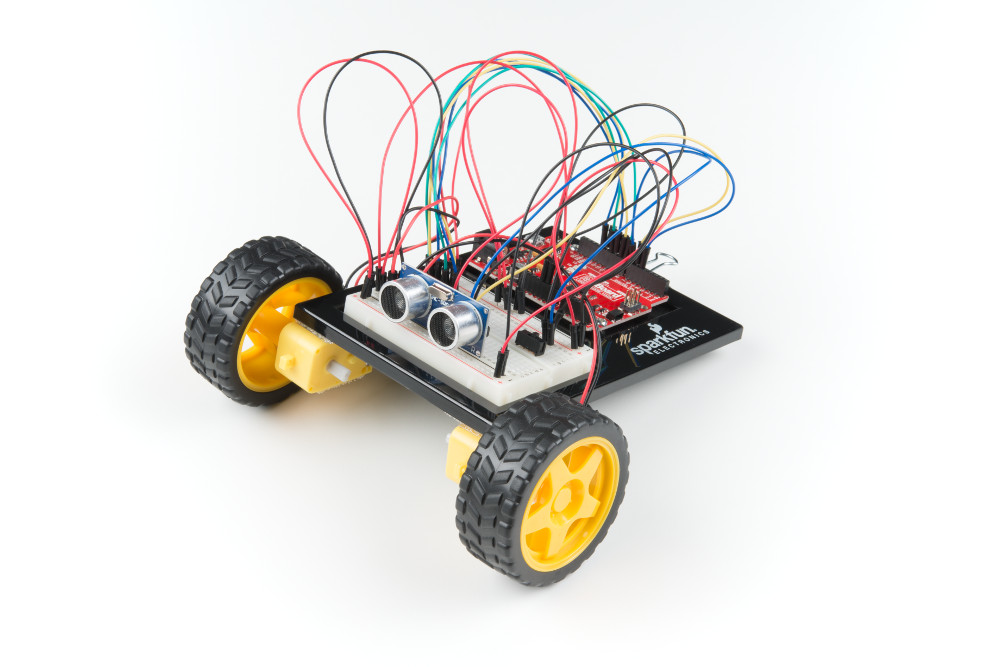
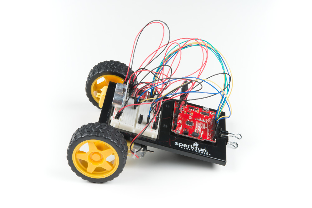
Circuit 5C: Autonomous Robot
Free the robots! In this circuit, you’ll unplug your robot and program it to navigate the world on its own. When the robot senses an object using the distance sensor, it will back up and change course.
Parts Needed
Grab the following quantities of each part listed to build this circuit:
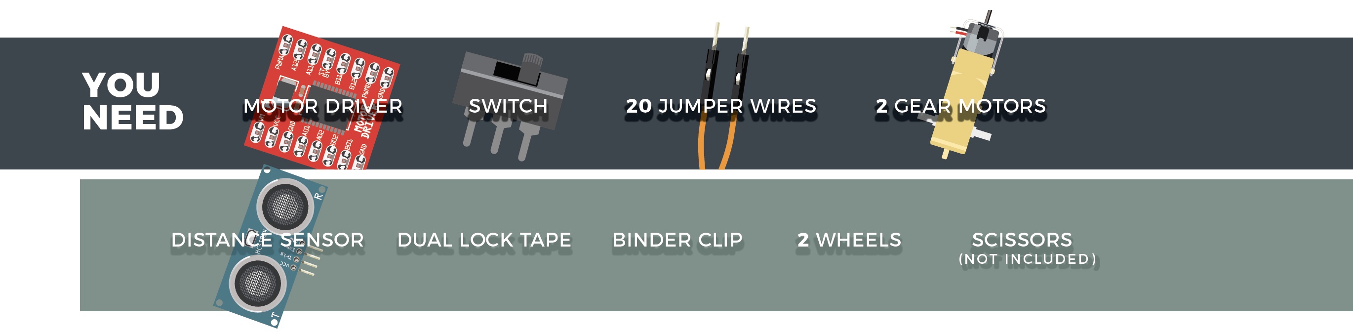
Additional Materials
- Scissors (NOT INCLUDED)
- 4x AA Batteries (NOT INCLUDED)
New Concepts
Autonomous Vehicles
The robot that you will build uses a simple sensor to avoid obstacles. This kind of system is used in Mars rovers, autonomous cars and the bots built for all kinds of robotics competitions. Understanding this example code will set you on the path to building bigger and better autonomous vehicles!
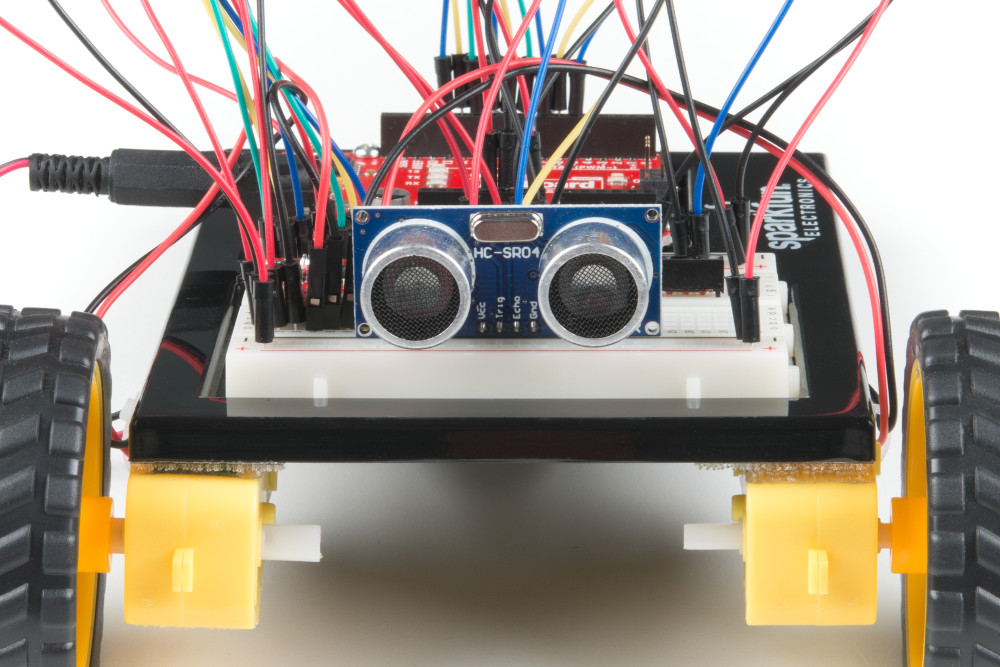
Hardware Hookup
| Polarized Components | Pay special attention to the component’s markings indicating how to place it on the breadboard. Polarized components can only be connected to a circuit in one direction. |
Keep in mind that the ultrasonic distance sensor needs a clear path to avoid unwanted interruptions in your robot's movements. Keep the distance sensor clear of any wires from your circuit.
Battery Holder Attachment
It's time to make this robot mobile by adding the battery pack.
If you did not attach the battery pack in Project 4, cut two pieces of Dual Lock that are about 1 inch x 1 inch (2.5cm x 2.5cm) each. Remove the adhesive backing and attach one piece to the back of the battery holder.
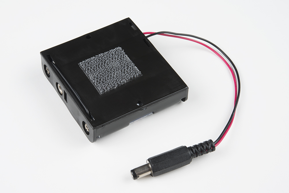
Adhere the second piece to the bottom of the baseplate, directly in the middle.
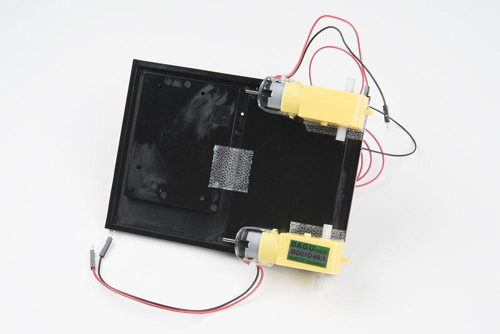
Press the battery holder to the baseplate so that the two pieces of Dual Lock snap together. Insert the batteries into the holder if you have not done so already. Remember that batteries are polarized and can only go in one way.
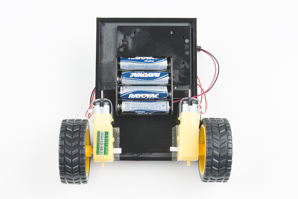
Clip the binder clip back on, and you are ready to roll!
You can choose to remove the motors and battery pack while you build the circuit or leave them on. The choice is yours.
Circuit Diagram
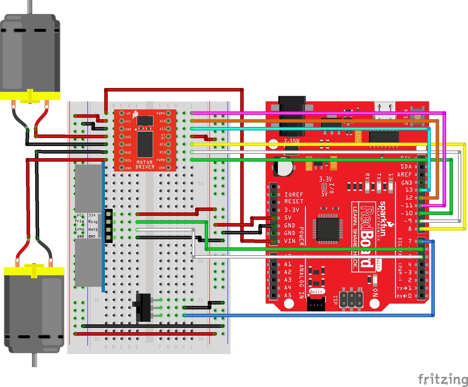
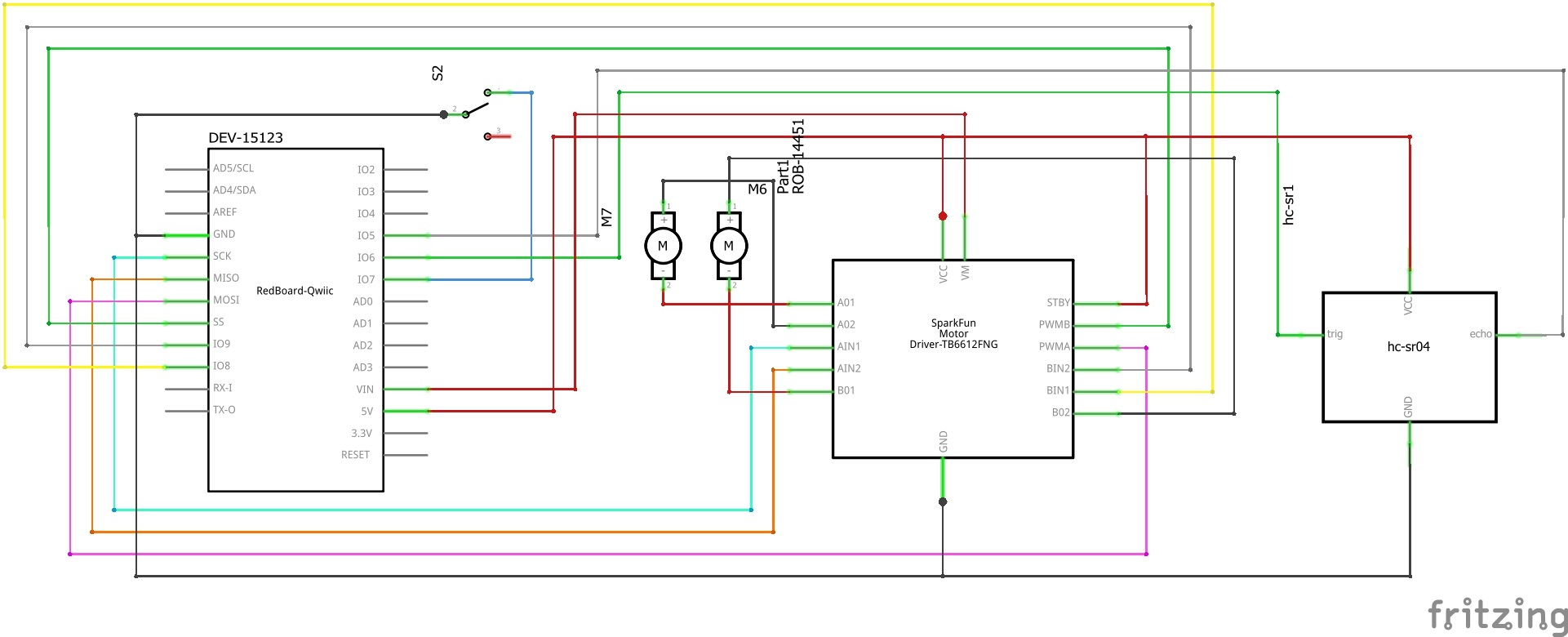
Having a hard time seeing the circuit? Click on the image for a closer look.
Hookup Table
| Component | RedBoard | Breadboard | Breadboard | Breadboard | Breadboard |
|---|---|---|---|---|---|
| Jumper Wire | 5V | 5V Rail ( + ) | |||
| Jumper Wire | GND | GND Rail ( - ) | |||
| Jumper Wire | 5V Rail ( + ) | 5V Rail ( + ) | |||
| Jumper Wire | GND Rail ( - ) | GND Rail ( - ) | |||
| Jumper Wire | VIN | A1 | |||
| Motor Driver | C1-C8 (VM on C1) |
G1-G8 (PWMA on G1) |
|||
| Jumper Wire | A2 | 5V Rail ( + ) | |||
| Jumper Wire | A3 | GND Rail ( - ) | |||
| Jumper Wire | Digital Pin 8 | J5 | |||
| Jumper Wire | Digital Pin 9 | J6 | |||
| Jumper Wire | Digital Pin 10 | J7 | |||
| Jumper Wire | J4 | 5V Rail ( + ) | |||
| Jumper Wire | Digital Pin 11 | J1 | |||
| Jumper Wire | Digital Pin 12 | J2 | |||
| Jumper Wire | Digital Pin 13 | J3 | |||
| Motor 1 (Right) | A4 (Red +) | A5 (Black -) | |||
| Motor 2 (Left) | A6 (Black -) | A7 (Red +) | |||
| Switch | F25 | F26 | F27 | ||
| Jumper Wire | I26 | GND Rail ( - ) | |||
| Jumper Wire | Digital Pin 7 | I27 | |||
| Distance Sensor | A14 (Vcc) | A15 (Trig) | A16 (Echo) | A17 (GND) | |
| Jumper Wire | Digital Pin 6 | E15 (Trig) | |||
| Jumper Wire | Digital Pin 5 | E16 (Echo) | |||
| Jumper Wire | E14 | 5V Rail ( + ) | |||
| Jumper Wire | E17 | GND Rail ( - ) |
Open the Sketch
To open the code, go to: File > Examples > SIK_Guide_Code-master > SIK_Circuit_5C-AutonomousRobot
You can also copy and paste the following code into the Arduino IDE. Hit upload, and see what happens!
language:c
/*
  SparkFun Inventor’s Kit
  Circuit 5C - Autonomous Robot

  This robot will drive around on its own and react to obstacles by backing up and turning to a new direction.
  This sketch was adapted from one of the activities in the SparkFun Guide to Arduino.
  Check out the rest of the book at
  https://www.sparkfun.com/products/14326

  This sketch was written by SparkFun Electronics, with lots of help from the Arduino community.
  This code is completely free for any use.

  View circuit diagram and instructions at: https://learn.sparkfun.com/tutorials/sparkfun-inventors-kit-experiment-guide---v41
  Download drawings and code at: https://github.com/sparkfun/SIK-Guide-Code
*/


//the right motor will be controlled by the motor A pins on the motor driver
const int AIN1 = 13;           //control pin 1 on the motor driver for the right motor
const int AIN2 = 12;            //control pin 2 on the motor driver for the right motor
const int PWMA = 11;            //speed control pin on the motor driver for the right motor

//the left motor will be controlled by the motor B pins on the motor driver
const int PWMB = 10;           //speed control pin on the motor driver for the left motor
const int BIN2 = 9;           //control pin 2 on the motor driver for the left motor
const int BIN1 = 8;           //control pin 1 on the motor driver for the left motor


//distance variables
const int trigPin = 6;
const int echoPin = 5;

int switchPin = 7;             //switch to turn the robot on and off

float distance = 0;            //variable to store the distance measured by the distance sensor

//robot behaviour variables
int backupTime = 300;           //amount of time that the robot will back up when it senses an object
int turnTime = 200;             //amount that the robot will turn once it has backed up

/********************************************************************************/
void setup()
{
  pinMode(trigPin, OUTPUT);       //this pin will send ultrasonic pulses out from the distance sensor
  pinMode(echoPin, INPUT);        //this pin will sense when the pulses reflect back to the distance sensor

  pinMode(switchPin, INPUT_PULLUP);   //set this as a pullup to sense whether the switch is flipped


  //set the motor control pins as outputs
  pinMode(AIN1, OUTPUT);
  pinMode(AIN2, OUTPUT);
  pinMode(PWMA, OUTPUT);

  pinMode(BIN1, OUTPUT);
  pinMode(BIN2, OUTPUT);
  pinMode(PWMB, OUTPUT);

  Serial.begin(9600);                       //begin serial communication with the computer
  Serial.print("To infinity and beyond!");  //test the serial connection
}

/********************************************************************************/
void loop()
{
  //DETECT THE DISTANCE READ BY THE DISTANCE SENSOR
  distance = getDistance();

  Serial.print("Distance: ");
  Serial.print(distance);
  Serial.println(" in");              // print the units

  if (digitalRead(switchPin) == LOW) { //if the on switch is flipped

    if (distance < 10) {              //if an object is detected
      //back up and turn
      Serial.print(" ");
      Serial.print("BACK!");

      //stop for a moment
      rightMotor(0);
      leftMotor(0);
      delay(200);

      //back up
      rightMotor(-255);
      leftMotor(-255);
      delay(backupTime);

      //turn away from obstacle
      rightMotor(255);
      leftMotor(-255);
      delay(turnTime);

    } else {                        //if no obstacle is detected drive forward
      Serial.print(" ");
      Serial.print("Moving...");


      rightMotor(255);
      leftMotor(255);
    }
  } else {                        //if the switch is off then stop

    //stop the motors
    rightMotor(0);
    leftMotor(0);
  }

  delay(50);                      //wait 50 milliseconds between readings
}

/********************************************************************************/
void rightMotor(int motorSpeed)                       //function for driving the right motor
{
  if (motorSpeed > 0)                                 //if the motor should drive forward (positive speed)
  {
    digitalWrite(AIN1, HIGH);                         //set pin 1 to high
    digitalWrite(AIN2, LOW);                          //set pin 2 to low
  }
  else if (motorSpeed < 0)                            //if the motor should drive backward (negative speed)
  {
    digitalWrite(AIN1, LOW);                          //set pin 1 to low
    digitalWrite(AIN2, HIGH);                         //set pin 2 to high
  }
  else                                                //if the motor should stop
  {
    digitalWrite(AIN1, LOW);                          //set pin 1 to low
    digitalWrite(AIN2, LOW);                          //set pin 2 to low
  }
  analogWrite(PWMA, abs(motorSpeed));                 //now that the motor direction is set, drive it at the entered speed
}

/********************************************************************************/
void leftMotor(int motorSpeed)                        //function for driving the left motor
{
  if (motorSpeed > 0)                                 //if the motor should drive forward (positive speed)
  {
    digitalWrite(BIN1, HIGH);                         //set pin 1 to high
    digitalWrite(BIN2, LOW);                          //set pin 2 to low
  }
  else if (motorSpeed < 0)                            //if the motor should drive backward (negative speed)
  {
    digitalWrite(BIN1, LOW);                          //set pin 1 to low
    digitalWrite(BIN2, HIGH);                         //set pin 2 to high
  }
  else                                                //if the motor should stop
  {
    digitalWrite(BIN1, LOW);                          //set pin 1 to low
    digitalWrite(BIN2, LOW);                          //set pin 2 to low
  }
  analogWrite(PWMB, abs(motorSpeed));                 //now that the motor direction is set, drive it at the entered speed
}

/********************************************************************************/
//RETURNS THE DISTANCE MEASURED BY THE HC-SR04 DISTANCE SENSOR
float getDistance()
{
  float echoTime;                   //variable to store the time it takes for a ping to bounce off an object
  float calculatedDistance;         //variable to store the distance calculated from the echo time

  //send out an ultrasonic pulse that's 10ms long
  digitalWrite(trigPin, HIGH);
  delayMicroseconds(10);
  digitalWrite(trigPin, LOW);

  echoTime = pulseIn(echoPin, HIGH);      //use the pulsein command to see how long it takes for the
                                          //pulse to bounce back to the sensor

  calculatedDistance = echoTime / 148.0;  //calculate the distance of the object that reflected the pulse (half the bounce time multiplied by the speed of sound)

  return calculatedDistance;              //send back the distance that was calculated
}
What You Should See:
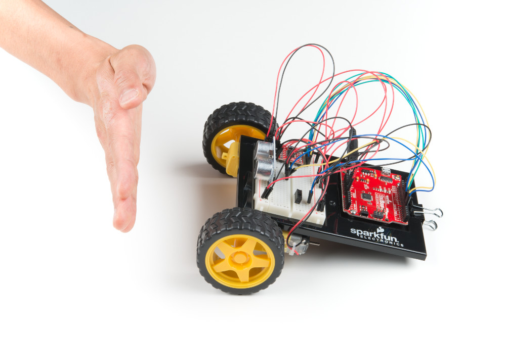
When the switch is turned off, the robot will sit still. When the switch is turned on, the robot will drive forward until it senses an object.
When it does, it will stop, back up and turn to the right before driving forward again.
Program Overview
- If the switch is turned on,
- Then start sensing the distance. a. If no obstacle is detected, then drive forward. b. If an obstacle is detected, stop, back up, and turn right. c. If no obstacle is detected, start driving forward again.
Code to Note
This code builds upon all the concepts you've learn in all the previous projects. There are no new functions or objects.
Coding Challenges
| Challenge | Description |
|---|---|
| Change the distance at which your robot reacts | Try changing the distance at which your robot stops and turns away from an obstacle. |
| Change the behavior of the robot when it senses an obstacle | Try changing the code so that your robot does something different when it senses an obstacle. |
Troubleshooting
| Problem | Solution |
|---|---|
| The robot drives backward and/or turns in the wrong direction | Check the wiring of your motors and the way that they are mounted to the breadboard and Arduino holder. If one of your motors is flipped around, reposition it, or switch its black and red wires on the breadboard (this will reverse the direction that it turns). |
| The robot runs into obstacles | You can try gently bending the pins of the distance sensor so that it points farther up, away from the floor. The robot will get stuck if one wheel hits an object that it is driving past (the distance sensor won’t see the obstacle unless it’s in front of the robot). |
| The robot drives backward and turns when there are no obstacles | Make sure the wires are not in front of the distance sensor. Also make sure you are not in a room with large HVAC vents. As in Project 3, these vents can wreak havoc on the ultrasonic distance sensor. |
| The robot drives slow or not at all, though the RedBoard is powered | If your board is powered but the robot is slow, won't move at all, or is behaving sporadically, check the batteries. These behaviors are symptoms of low or dead batteries. |
| Still not working? | Jumper wires unfortunately can go "bad" from getting bent too much. The copper wire inside can break, leaving an open connection in your circuit. If you are certain that your circuit is wired correctly and that your code is error-free and uploaded but you are still encountering issues, try replacing one or more of the jumper wires for the component that is not working. |