SparkFun Inventor's Kit for micro:bit Experiment Guide
 D___Run___,
  bboyho
 Experiment 1: Blinking an LED
Introduction
LEDs are small, powerful lights that are used in many different applications. To start off, we will work on blinking an LED, the basic introduction of microcontrollers and building circuits. You already did a "Hello World" for the micro:bit itself, this is the next step. That's right --- it's as simple as turning a light on and off. It might not seem like much, but establishing this important baseline will give you a solid foundation as we work toward more complex experiments.
Parts Needed
You will need the following parts:
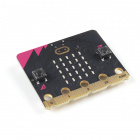
- 1x micro:bit
- 1x Micro B USB Cable
- 1x micro:bit Breakout (with Headers)
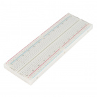
- 1x Breadboard
- 1x Jumper Wire
- 1x LED
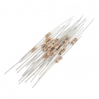
- 1x 100Ω Resistor
Didn't Get the SIK for micro:bit?
If you are conducting this experiment and didn't get the Inventor's Kit, we suggest using these parts:


Suggested Reading
Before continuing with this experiment, we recommend you be familiar with the concepts in the following tutorial:
- Light-Emitting Diodes --- Learn more about LEDs!
- How to Use a Breadboard --- Learn the basics of using a breadboard!
How to Use a Breadboard
May 14, 2013
Light-Emitting Diodes (LEDs)
August 12, 2013
Introducing the micro:bit Breakout
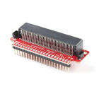
To extend the functionality of the micro:bit beyond what is already on the board, we developed a micro:bit breakout. For users with earlier versions of the SparkFun Inventor's Kit for micro:bit, users will be using the micro:bit Breakout Board as shown below on the left. Eventually the board had a revision as shown on below on the right. Don't worry, the overall functionality is the same. The difference is that the board includes a Qwiic enabled connector and surface mount edge connector. Throughout the tutorial, we will be using the micro:bit breakout board in the images and hookup diagrams.
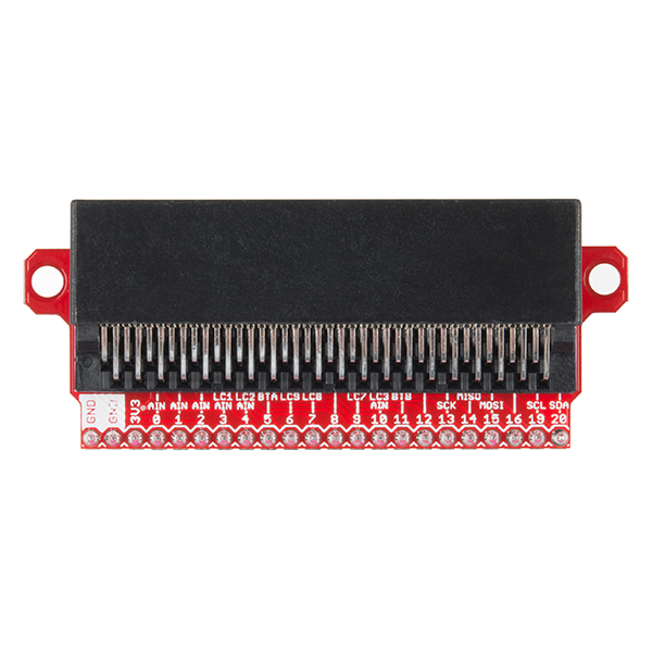 |
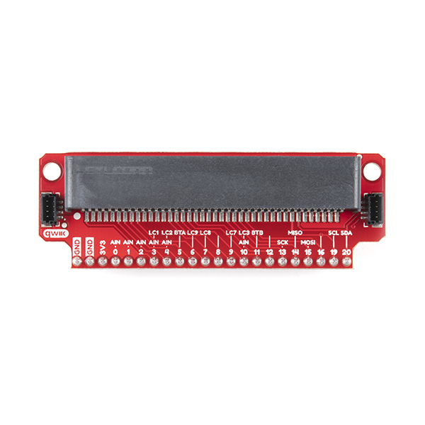 |
| micro:bit Breakout Board (with Headers) | Qwiic micro:bit Breakout Board (with Headers) |
This breakout board makes it much easier to use all of the pins available on the micro:bit edge connector in a more user-friendly way. We also broke out ground and VCC (3.3 volts) for your convenience.
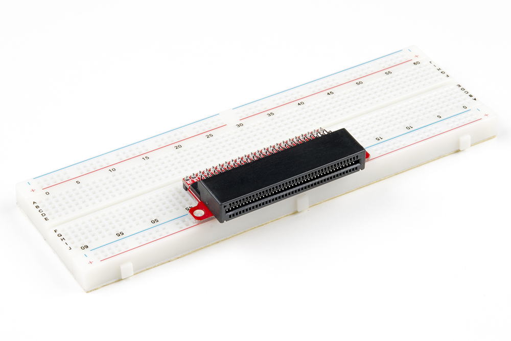
The breakout board lines up with the pins of a breadboard. We recommend using a full-sized breadboard with this breakout to give you enough room to prototype circuits on either end of the breadboard. Also, for durability's sake, insert the breakout pins about halfway into the breadboard so there is support under the board for when you insert a micro:bit and/or pull it out.
Introducing the LED
A Light-Emitting Diode (LED) will only let current through in one direction. Think of an LED as a one-way street. When current flows through the LED, it lights up!
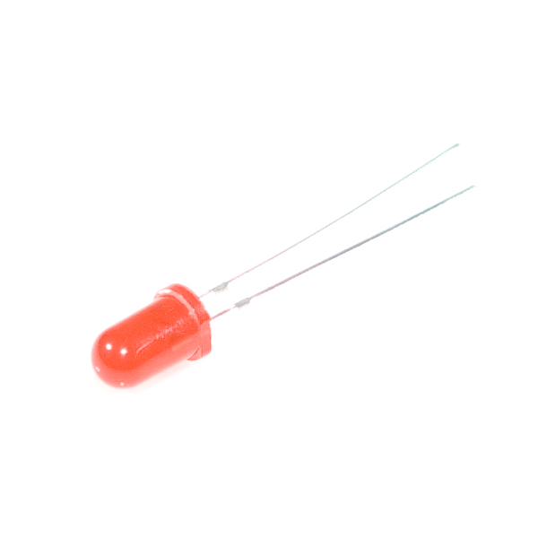
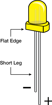
When you are looking at the LED, you will notice that its legs are different lengths. The long leg, the "anode," is where current enters the LED. This pin should always be connected to the current source. The shorter leg, the "cathode," is the current’s exit. The short leg should always be connected to a pathway to ground.
LEDs are finicky when it comes to how much current you apply to them. Too much current can lead to a burnt-out LED. To restrict the amount of current that passes through the LED, we use a resistor in line with the power source and the LED's long leg; this is called a current-limiting resistor. With the micro:bit, you should use a 100Ω resistor. We have included a baggy of them in the kit just for this reason!
Hardware Hookup
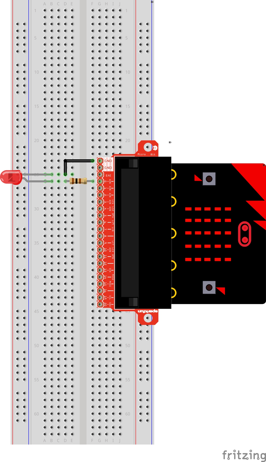
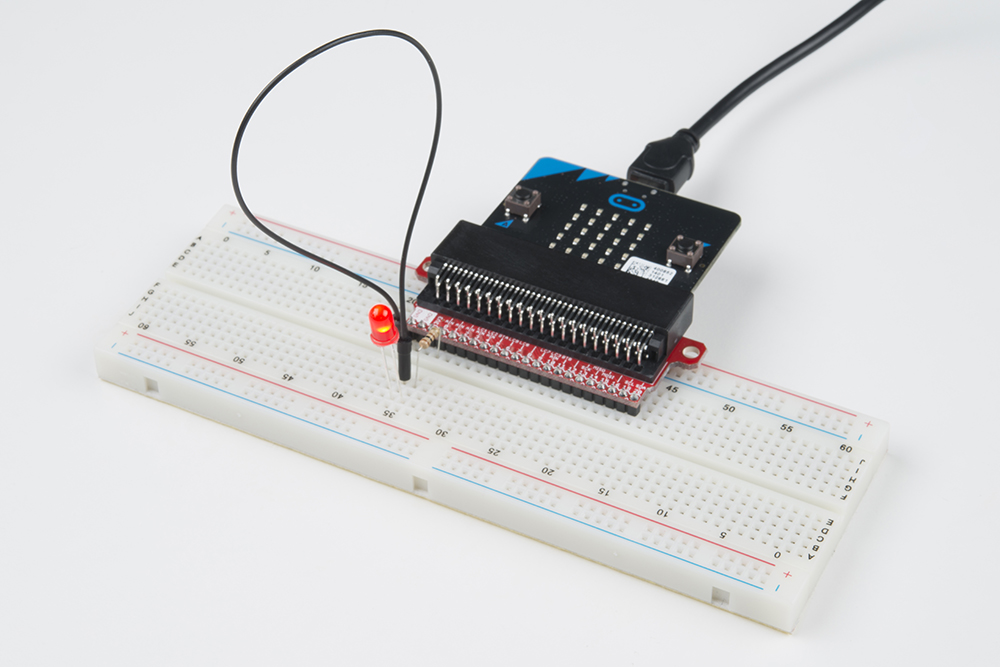
Ready to start hooking everything up? Check out the wiring diagram and hookup table below to see how everything is connected.
| Polarized Components | Pay special attention to the component’s markings indicating how to place it on the breadboard. Polarized components can only be connected to a circuit in one direction. |
Please note: Pay close attention to the LED. The negative side of the LED is the short leg, marked with a flat edge.
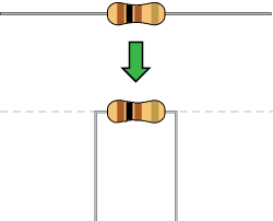
Components like resistors need to have their legs bent into 90° angles in order to correctly fit the breadboard sockets. You can also cut the legs shorter to make them easier to work with on the breadboard.
Wiring Diagram for the Experiment
Running Your Script
Either copy and paste, or re-create the following code into your own MakeCode editor by clicking the open icon in the upper right-hand corner of the editor. You can also just download this example by clicking the download button in the lower right-hand corner of the code window.
Code to Note
Let's take a look at the code blocks in this experiment.
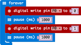
Forever
The forever block is a block that loops any other command blocks inserted into it over and over again...forever. It starts from the top and executes your code in order working its way to the bottom and then starts at the top again.
Digital Write
The DigitalWrite block enables you to turn a pin on or off. There is a dropdown option for which pin you want to control, and it accepts a variable as the pins state. You use 1 as on and 0 as off. If you prefer, you can also use Boolean states of true and false, but we will use 0 and 1 as our standard throughout this guide.
Pause
If you were to just turn pins on and off with the digital write block without a pause, the LED would blink really, really fast. The pause block enables you to slow the micro:bit down and lets you control the timing of things happening. It accepts a number or variable as the number of milliseconds you want the micro:bit to pause. Think of this block as a stoplight for your code!
Led > more > led enable false . For more information on the GPIO pins reserved for the LED array, check out the link below.
What You Should See
You should see your LED blink on and off at 1-second intervals. If it doesn't, make sure you have assembled the circuit correctly and verified and uploaded the code to your board, or see the Troubleshooting section.
Troubleshooting
LED Not Blinking
Make sure you have it wired correctly and the correct pin to ground. Remember, short pin to ground; long pin to signal.
Still No Success
A broken circuit is no fun. Send us an email, and we will get back to you as soon as we can: techsupport@sparkfun.com .