SparkFun Inventor's Kit for MicroView
 Joel_E_B
Quick Start Experiment
The MicroView comes with preinstalled code to get you learning right out of the box without having to do any programming. Using just a few components, you can learn the in's and out's of the MicroView.
Setting Up Your MicroView
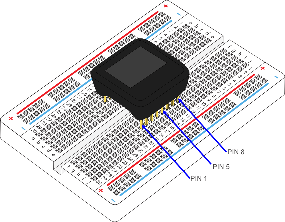
Identify PIN 1 of MicroView based on the following diagram, or refer back to the MicroView Overview section.
MicroView with USB Programmer
The quickest way to get started is to use the USB programmer.
Insert the MicroView to the USB Programmer, then connect the female end of the USB extension cable to the factory USB Programmer.
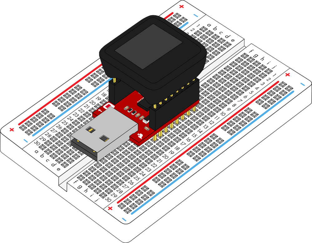
Connect the male end of the USB extension cable to the computer. The MicroView will power on, and the demo will start.
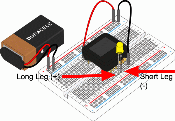
MicroView without USB Programmer
If you would like to use the MicroView without the USB Programmer, you will need the following (please note that the 9V battery and snap connector will need to be purchased separately):
- 9V Battery
- 9V Snap Connector (Remove the Molex connector, replace both wires with male header pins if necessary)
Connect the required parts based on the diagram below. Plug in the battery connectors last. Once plugged in, the 9V battery will power the MicroView through the VIN pin (PIN 1).
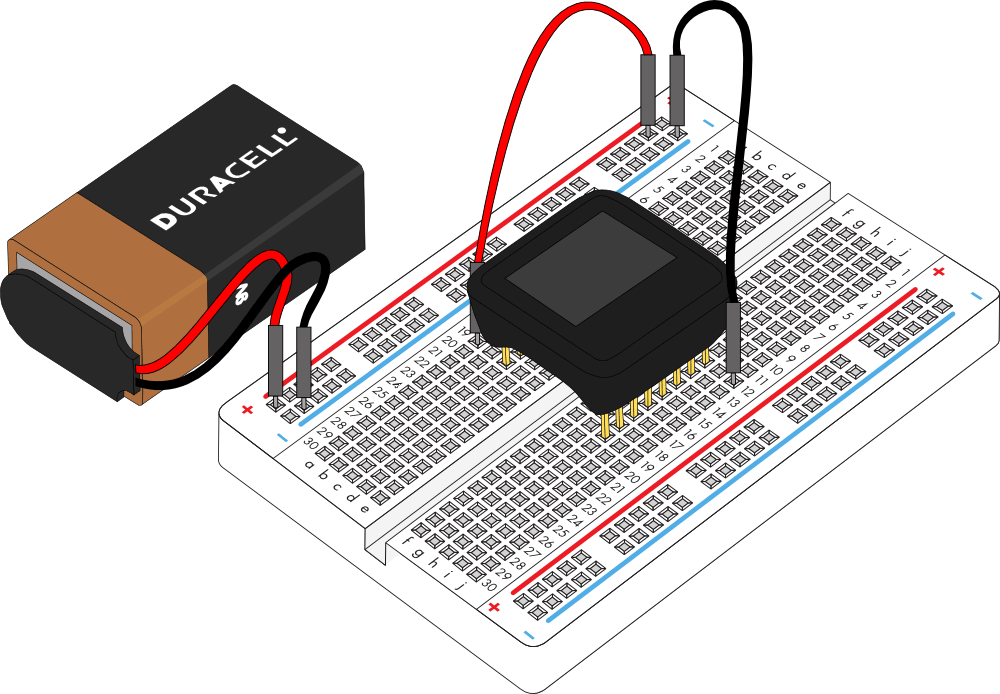
As soon as the MicroView is powered, the demo will start.
Learn How to Use MicroView
The MicroView comes pre-programmed with a few simple built-in tutorials to help you get use to inserting jumper wires, resistors and an LED. Skip these tutorials if you are already familiar with them. They will begin after the visual demo.
Simple Tutorial 1
Follow the instruction displayed on the MicroView, and connect PIN 5 and PIN 8 of the MicroView with a jumper using the following diagram as reference:

Once you have successfully connected PIN 5 and PIN 8 of the MicroView, a “Well done!” message will be displayed. To proceed to the next simple tutorial, remove the jumper.
Simple Tutorial 2
Follow the instruction displayed on the MicroView, and connect PIN 3 and PIN 8 of the MicroView with a jumper using the following diagram as reference:

Once you have successfully connected PIN 3 and PIN 8 of the MicroView, a “Well done!” message will be displayed. To proceed to the next simple tutorial, remove the jumper.
Simple Tutorial 3
Follow the instruction displayed on the MicroView, and connect PIN 2 and PIN 8 of the MicroView with a jumper using the following diagram as reference:

Once you have successfully connected PIN 2 and PIN 8 of the MicroView, a “Well done!” message will be displayed. To proceed to the next simple tutorial, remove the jumper.
Simple Tutorial 4
Follow the instruction displayed on the MicroView, and connect PIN 4 and PIN 8 of the MicroView with a 330Ω resistor using the following diagram as reference:

Once you have successfully connected PIN 4 and PIN 8 of the MicroView with the resistor, a “Well done!” message will be displayed. To proceed to the next simple tutorial, remove the resistor.
Simple Tutorial 5
Follow the instruction displayed on the MicroView, and connect PIN 4 and PIN 8 of the MicroView with a 10KΩ resistor using the following diagram as reference:

Once you have successfully connected PIN 4 and PIN 8 of the MicroView with the resistor, a “Well done!” message will be displayed. To proceed to the next simple tutorial, remove the resistor.
Simple Tutorial 6
Follow the instruction displayed on the MicroView, connect PIN 5 and PIN 8 of the MicroView with a 330Ω resistor using the following diagram as reference:

With the resistor still at the same place, insert an LED with both of the pins at PIN 4 and PIN 5 of MicroView respectively using the following diagram as reference.
The MicroView is able to detect if the LED is inserted with the correct polarity, and it will begin blinking the LED.
If the LED does not blink, remove the LED and turn the pins the other way round and connect them to PIN 4 and PIN 5 of the MicroView.
With that, you are now ready to upload code and begin building the experiments in this guide.
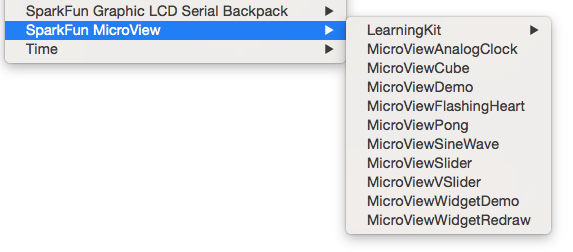
If you would like to load the Demo Sketch back on to the MicroView after you have uploaded any other code, you can find the MicroViewDemo.ino sketch in the MicroView Library Examples.