SparkFun NanoBeacon Board - IN100 Hookup Guide
 El Duderino
 Introduction
The SparkFun NanoBeacon Board - IN100 and SparkFun NanoBeacon Lite Board - IN100 offer a 2.4 GHz wireless low energy beacon breakout with exceptional low power consumption features and minimal programming required. The two versions allow for you to prototype with the Lite (Development) version and then employ the Standard (Production) version in large installations once your hardware and software design is complete. The board features the IN100 NanoBeacon™ from InPlay™. The NanoBeacon Config Tool allows for software-free programming of the modules removing any need to perform any tricky programming for advertising settings to send and receive packets.
While both versions of this board use the same design, there are a few minor differences between them. The Lite version of this breakout is intended for prototyping and includes a reset button and power LED. The standard version is designed with rapid implementation requiring minimal assembly and modification so it does not have the reset button or power LED populated and has male headers soldered to board's through-hole pins.
In this guide we'll take a look at the IN100 and other hardware present on these boards, how to assemble and configure them using the NanoBeacon Config Tool as well as an example demonstrating how to use these beacons with the Qwiic BMA400.
The Config Tool offers a testing "Run in RAM" mode for many settings but I2C is not available in the RAM testing mode. Users connecting I2C devices to the board should ensure their code works before clicking the "Burn/Program" button.
Required Materials
Along with either version of the beacon, you'll need a serial-to-UART converter for initial device configuration. After configuring the IN100 you'll want something to pair it with like a development board. The beacon also requires a coin cell battery for power.
Required Tools
Some soldering may be required if you're using the Lite version. In case you need some soldering tools or components, check out the products below:


Additional Materials
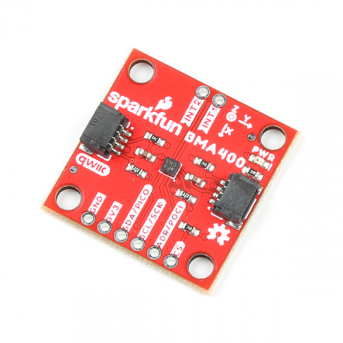
In the examples section of this guide we'll show how to send motion data recorded by the BMA400 on the SparkFun Triple Axis Accelerometer Breakout - BMA400 (Qwiic) to a SparkFun RedBoard IoT. If you want to follow along with this example, you'll want to pick one up:
Suggested Reading
This board features a Qwiic connector for use with our ever-expanding Qwiic ecosystem. If you're not familiar with Qwiic, we recommend you head over to this page for more information.
You may also want to read through the tutorials below if you are not familiar with the concepts covered in them or would like a refresher:
Serial Communication
Hardware Overview
Let's take a closer look at the IN100 and other hardware on these NanoBeacon boards.
IN100 NanoBeacon
The NanoBeacon IN100 SoC from InPlay is an ultra low power BT beacon module compatible with common 2.4 GHz protocols.
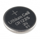
The IN100 boasts impressive features to reduce power consumption of the module to well below a microamp allowing it to be left in the field sending data packets for multiple years on a single coin cell battery. The IN100 accepts a supply voltage from 1.1-3.6V so it can be reliably powered by a 3V CR1225 and has three power modes: Sleep, Active and Shut Down. The 2.4 GHz radio has programmable TX output power up to +5 dBm.
The module can also be configured to act as a Google™ Eddystone™ and Apple® iBeacon® compliant device. For a complete overview of the IN100, refer to the module's datasheet.
The IN100 includes the following peripheral options:
- One UART,
- Eight GPIO pins (four with multiple function options including I2C and ADC)
- 11-bit ADC for measuring chip temperature and Vcc voltage with four channels available on GPIOs
- Two load switches for controlling power to peripheral devices
- Pulse count interface compatible with one-wire sensors.
These options let users connect a wide assortment of peripheral devices to the NanoBeacon and then broadcast the data wirelessly to other devices.
Through Hole Headers
The breakouts route most of the IN100's pins to a pair of 0.1"-spaced plated through hole (PTH) headers. The standard version comes with two male headers soldered to these pins.
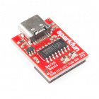
One side has a UART interface to mate with a 3.3V Serial Basic (or similar UART to Serial converter) for USB communication and configuring the IN100 through the Config Tool.
The other side breaks out four of the IN100's GPIO pins (pins 4-7) as well as the two I/O power switches (SW0 and SW1).
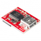
Qwiic Connector
The Qwiic connector on the board uses I/O pins 3 and 4 for SDA and SCL, respectively. Using this connector requires enabling I2C on the IN100 in the Config Tool.
The board design allows for the IN100 to control both communication and power to a connected Qwiic device so you can configure the IN100 to toggle power a device on for a quick measurement and back off to conserve power. By default, power to the Qwiic connector is controlled by the Switch 0 (SW0) pin allowing users to toggle power on and off to a connected Qwiic device. Users who prefer to have a Qwiic device continuously powered from Vcc can adjust the BUS jumper. Read on to the Solder Jumpers section for more information.
Power Options
The NanoBeacon Boards have two power options: coin cell battery or Vcc on the UART header.
Battery Holder
The breakout includes a 12mm coin cell battery holder to power the board. Use only 3V CR1225 batteries in this holder. The IN100 supply voltage range goes all the way down to 1.1V so, with the right settings, the board can run off a coin cell battery until it is essentially completely drained.
UART Header
The IN100 can also be powered directly through the VCC pin from a dedicated power supply or over USB when connected to a USB to Serial converter like the Serial Basic. Make sure the voltage here falls into the IN100's supply voltage range (1.1-3.6V).
Reset Button
The Lite version includes a Reset button for quickly resetting the board during prototyping.
LED
The sole LED on this board is the Power LED indicating power to the board. The Production version of this breakout does not include this LED to help conserve power and reduce customization time.
Solder Jumpers
The Beacon Breakout includes three solder jumpers labeled: PWR, I2C, and BUS. The table below outlines their labels, default state, function and any notes on their use.
| Label | Default State | Function | Notes |
|---|---|---|---|
| PWR | CLOSED | Completes Power LED circuit | Open to disable the Power LED |
| I2C | CLOSED | Three-way jumper that pulls IO3 and IO4 (SDA/SCL) to Vcc | Open completely to disable the pull up resistors on these lines |
| BUS | SEE NOTE | Three-way jumper controlling IO power source | By default, this nets Qwiic Vcc to SW0 to toggle power to the connector. Sever the trace connecting the center and "SW" pad and solder the center and "VCC" pad together to switch to Qwiic power supply to Vcc (always on). |
Notes Pad
Last but not least, the NanoBeacon boards include a "Notes" pad for users to write on. This lets you quickly differentiate between NanoBeacon boards to help keep track of them without needing to plug them into your computer.
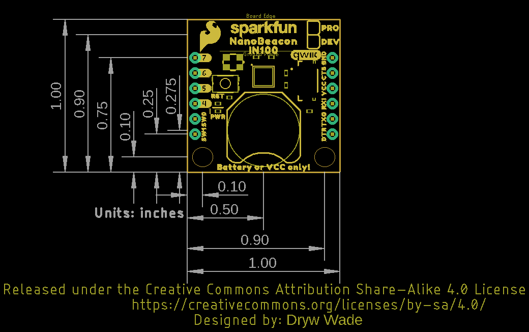
Board Dimensions
We designed the NanoBeacon boards to match our 1"x1"(25.4mm x 25.4mm) Qwiic standard and has two mounting holes that fit a 4-40 screw.
Hardware Assembly
Now that we're familiar with the hardware present on these NanoBeacon boards, we'll assemble our circuit for the Qwiic BMA400 example.
Solder
For this demo, we're using the Lite version of the NanoBeacon Board so we need to solder headers to the UART pins to connect a Serial Basic to for configuring the IN100 through the Config Tool.
Qwiic BMA400 Circuit
With headers soldered in place, connect the Serial Basic to them taking care to match the pins. At this point, you can also connect the Qwiic BMA400 to the Qwiic connector on the NanoBeacon Board. With everything connected, your circuit should be nearly identical to the one pictured below:
With our NanoBeacon Board assembled and connected to a Serial Basic, we can move on to plugging it into our computer and configuring the IN100 to test basic functionality and later upload the BMA400 data configuration file.
NanoBeacon Config Tool
InPlay's NanoBeacon Config Tool provides an easy, software-free GUI to configure and program the IN100. In this section we'll take a closer look at the features of the tool and a quick look at the basic set up required to have the beacon begin to advertise and transmit data packets.
This is just a quick overview of the Config Tool so for complete information on everything the tool offers, refer to InPlay's NanoBeacon Config Tool User Guide.
The Config Tool offers a testing "Run in RAM" mode for many settings but I2C is not available in the RAM testing mode. Users connecting I2C devices to the board should ensure their code works before clicking the "Burn/Program" button.
Download and Installation
You can get the Config Tool from InPlay's website:
If you want to use the InPlay scanner app on your phone, you can download it here as well. Depending on your operating system, you may need to install an unzipping tool. The Windows version is a 7-Zip file so users may need to install the 7-Zip Tool.
After downloading and uncompressing the files, navigate to the location you set, open the "NanoBeacon Tools" folder, and search for the "NanoBeaconConfigTool" application to open the program.
Config Tool GUI
With the Config Tool open, let's take a quick look at some of the features of the Config Tool:
The first thing you want to take note of is the UART box in the top-right of the GUI. This is where you'll select the Port your Serial Basic or other Serial-to-UART is connected to. Click the "Probe" button, select the correct port and click "Connect" (If you're not sure which port is correct, disconnect and reconnect the Serial Basic and check which port disappears/appears).
From here you can configure all sorts of settings and enable different features in the tabs on the left labeled "Application Settings". For now, we're going to move on to a basic, "Hello World" functionality test to make sure the IN100 is working properly.
"Hello World" Test
As a simple functionality test, we'll perform a basic configuration of the IN100 to set it up as an Eddystone device we can scan for using the InPlay scanner app (or other scanner app such as nRF Connect).
For this test we're going to set up the IN100 to operate as a bare-bones Eddystone device but you can select a different option if you prefer. For this test, select the "Advertising" tab under "Application Settings" and click the "Edit" button for "Advertising Set #1". In the "Advertising Data" tab select "Eddystone" and then click "Ok". This default setting works fine for our quick functionality test but if you do use the NanoBeacon as an Eddystone device in a more permanent setting, make sure to follow their guidelines linked in the note below.
With the advertising settings confirmed, click the "Run in RAM" button and open the InPlay scanner app or your chosen alternate application and the NanoBeacon should show up as an Eddystone device with the name "N/A".
BMA400 Qwiic Example
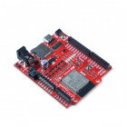
Now that we know the IN100 is working and advertising, let's use a custom config file to send acceleration data from the SparkFun Triple Axis Accelerometer Breakout - BMA400 (Qwiic) to a RedBoard IoT running code to convert the values into a serial printout.
Required Libraries & Board Tools
This example assumes the use of the SparkFun IoT RedBoard board file as well as several libraries that do not come pre-installed with Arduino. Make sure to install both the board files and libraries prior to using this example. The SparkFun IoT RedBoard uses the ESP32 Dev Module board definition included in the "esp32" boards package. For detailed information on installing and using the IoT RedBoard, check out this section of our Hookup Guide for the board. Install the libraries used in this example with the Arduino Library Manager tool by searching for "ESP32 BLE Arduino".
Qwiic BMA400 Config File
With the board files and libraries installed we can move on to loading the Qwiic BMA400 config file from the Examples folder in the GitHub repository. This also contains the Arduino code so go ahead and download both (or the whole repository).
This config file contains all of the I2C commands as well as custom advertising data settings to name the NanoBeacon "BMA400_Data" and have it send voltage and I2C data. You can modify this if necessary but for a quick personal test, these settings should be just fine. You can view the I2C commands in the "I2C" window as shown below:
After loading the config file and adjusting anything you see fit, click the "Burn/Program" button. Reminder, this is a one-time use button and there is no confirmation prompt. Any settings here are saved permanently to the IN100 so if you do change anything here, make sure it works before clicking this button.
Arduino Code
With just the config file loaded on the NanoBeacon, you can open up a scanner app and watch the acceleration data print out in hex but that isn't very human-readable. To convert this hex data to a serial print, we wrote a quick Arduino sketch that connects to a NanoBeacon board running the config file we just uploaded and then parses the hex data into a serial print to easily ready acceleration data from all three of the BMA400's axes.
Open the sketch file or copy the code below into a blank Arduino sketch. Select your board (in our case "ESP32 Dev Module") and Port and click the upload button.
language:c
#include <BLEDevice.h>
#include <BLEUtils.h>
#include <BLEScan.h>
#include <BLEAdvertisedDevice.h>
#include <BLEEddystoneURL.h>
#include <BLEEddystoneTLM.h>
#include <BLEBeacon.h>

int scanTime = 1;
BLEScan *pBLEScan;

// This class is used for the onResult() callback function
class MyAdvertisedDeviceCallbacks : public BLEAdvertisedDeviceCallbacks
{
  // This function is called each time a new BLE device is found during a scan
  void onResult(BLEAdvertisedDevice advertisedDevice)
  {
    // Some BLE devices don't have names, so we'll ignore the ones that don't
    if (advertisedDevice.haveName())
    {
      // Check if the name of this device matches our beacon
      const char* deviceName = advertisedDevice.getName().c_str();
      if(strncmp(deviceName, "BMA400_Data", strlen(deviceName)) == 0)
      {
        // This is our beacon! Print out the received signal strength
        Serial.printf("RSSI: %i\n", advertisedDevice.getRSSI());

        // Copy the manufacturer data into a buffer
        uint8_t manufacturerData[32];
        std::string manufacturerDataString = advertisedDevice.getManufacturerData();
        manufacturerDataString.copy((char*) manufacturerData, manufacturerDataString.length(), 0);

        // The first 2 bytes are the manufaturer ID, print those out
        uint16_t manufacturerID = (manufacturerData[0] << 8 ) | manufacturerData[1];
        Serial.printf("Manufacturer ID: %04X\n", manufacturerID);

        // The next byte is the battery voltage, units are 31.25mV/LSB
        uint16_t voltageRaw = manufacturerData[2];
        float voltage = voltageRaw * 0.03125;
        Serial.printf("Voltage: %.2f\n", voltage);

        // Last 6 bytes are the raw acceleration data for the x/y/z axes, as specified in the BMA400 datasheet
        int16_t xRaw = ((uint16_t) manufacturerData[4] << 8) | manufacturerData[3];
        int16_t yRaw = ((uint16_t) manufacturerData[6] << 8) | manufacturerData[5];
        int16_t zRaw = ((uint16_t) manufacturerData[8] << 8) | manufacturerData[7];

        // The raw values are 12-bit signed values, so we need to make sure negative values are correctly signed
        if(xRaw > 2047) xRaw -= 4096;
        if(yRaw > 2047) yRaw -= 4096;
        if(zRaw > 2047) zRaw -= 4096;

        // Convert the raw values to acceleration in g's
        // BMA400 defaults to +/- 4g over the whole 12-bit range
        float xAcc = xRaw * 4.0 / pow(2, 11);
        float yAcc = yRaw * 4.0 / pow(2, 11);
        float zAcc = zRaw * 4.0 / pow(2, 11);

        // Now print out the x/y/z acceleration values
        Serial.printf("X: %.2f Y: %.2f Z: %.2f\n\n", xAcc, yAcc, zAcc);

        // Now that we've found our beacon and logged everything, we can stop the scan
        pBLEScan->stop();
      }
    }
  }
};

void setup()
{
  // Set up serial
  Serial.begin(115200);
  Serial.println("BLE scan sketch begin!");

  // Create new BLE scan object
  BLEDevice::init("");
  pBLEScan = BLEDevice::getScan();

  // Set callback for when new devices are found in the scan
  pBLEScan->setAdvertisedDeviceCallbacks(new MyAdvertisedDeviceCallbacks());

  // Enable active scanning. It uses more power, but is faster
  pBLEScan->setActiveScan(true);

  // Set the scan interval and window in milliseconds
  pBLEScan->setInterval(100);
  pBLEScan->setWindow(99);
}

void loop()
{
  // Start new scan. This blocks until finished
  BLEScanResults foundDevices = pBLEScan->start(scanTime, false);

  // Scan finished, delete results to release memory
  pBLEScan->clearResults();
}
After uploading, open the serial monitor with the baud set to 115200. The code will start to scan for the matching NanoBeacon device (BMA400_Data) and when it succeeds, prints out the data sent by the beacon including Manufacturer ID, voltage measured on Vcc and the acceleration data of the x/y/z axes.
Additional Config Tests
For those who want to go beyond this example or prefer to send I2C data from different devices, InPlay has a growing list of other config tests for other sensors, like the BME280 atmospheric sensor, available from the GitHub repository below:
Troubleshooting
NanoBeacon and NanoBeacon Lite Version Differences
As we covered before, the two versions of the NanoBeacon board share the same design but with a few different features.
NanoBeacon
- Pre-Soldered Male Headers
- Power LED not included
- Reset Button not included
NanoBeacon Lite
- No Male Headers
- Power LED
- Reset Button
NanoBeacon Config Tool Tips
Here are a couple of tips we found useful while working with the NanoBeacon Config Tool
One-Time Burn/Program
One final reminder, the "Burn/Program" button is a permanent action and does NOT have a confirm prompt. Make sure to test any settings you can in the "Run in RAM" option to confirm everything is working and configured properly before pressing the "Burn/Program" button.
Reset Button
Sometimes the Config Tool will not be able to connect to the IN100 after running things in RAM. We found disconnecting the device in the program and reconnecting works in most cases. If it still gets stuck, push the Reset button on the Lite version or power cycle the standard version and it should resolve the issue.
NanoBeacon Advertising Settings Guidelines
All three advertising setting options (Eddystone, iBeacon, and Custom) should adhere to the protocol guidelines for each mode. Make sure to follow the guidelines for your selected mode by referring to their documentation linked below:
Increasing NanoBeacon Performance and Range
If you really need to squeeze out a little more performance from this board, InPlay suggests adjusting a couple of settings in the "XO" option under "Global Settings". First, changing the Internal Capacitor Code from 8 to 11 can add roughly 5-10dB performance which can help increase the range of the IN100. Second, changing the Strength Code from 16 to 19 should also help with overall performance.
Resources and Going Further
That's all for this tutorial. For more information about the NanoBeacon Boards - IN100 and InPlay's NanoBeacon Config Tool, check out the resources below.
NanoBeacon Board Resources
- Schematics
- Eagle Files
- Board Dimensions
- Hardware GitHub Repository
IN100 NanoBeacon Resources