SparkFun Qwiic Button Hookup Guide
 El Duderino
Arduino Examples
In this section we will go over a few of the examples from our Qwiic Button Arduino Library. Here is a full list of all the examples included in the library:
- Example 1 - Prints the button status.
- Example 2 - Turns the button LED on while the button is pressed.
- Example 3 - Pulses the button LED while the button is pressed.
- Example 4 - Demonstrates how to use the FIFO Queue and returns time elapsed since button presses.
- Example 5 - Details how to identify and change the I2C address.
- Example 6 - I2C Bus Configuration. Useful for devices with multiple I2C ports.
- Example 7 - Sets up 2 Qwiic Buttons and reads their statuses.
- Example 8 - Configures the button to toggle the interrupt pin when pressed.
Example 1: Print Button Status
The code for Example1_PrintButtonStatus connects the Qwiic Button to the I2C bus and prints the status of the button (pressed or not pressed) to the Serial Monitor.
Example 3 Pulse When Pressed
Example3_PulseWhenPressed connects the Qwiic Button to the I2C bus and runs the Button LED through a configured sequence when the button is pressed. The code configures the LED settings for brightness, cycleTime and offTime to pulse the Button LED while it is pressed. Try playing around with these settings to change the behavior of the LED.
Example 4 Queue Usage
Example4_QueueUsage demonstrates how to call, check, and alter the FIFO Queue for a button press and button click. The code will check both the Pressed and Clicked queues and, if the queue is not empty, prints over serial the time since the first press (since the queue was last cleared) and the time since the last press. Entering "P" in the serial monitor will "pop" the Pressed Queue to return the oldest value stored in the queue and then remove it. Entering "C" will perform the same action for the Clicked Queue.
Example 5 Change I2C Address
Example5_ChangeI2CAddress checks to initialize the Qwiic Button on the I2C bus. If the device ID matches what is expected (0x6F by default), it then will print some helpful information for changing the I2C address and prompt you for an input to change the address. Once a new device ID is input and is valid, the code writes the new I2C address to EEPROM on the ATtiny84 and prints out a success note along with the new device ID. If the entered address is invalid or for some reason the write fails, the code will print out an error detailing what failed.
If the device ID does not match what is expected, it runs a scan for devices on the bus and prints out the ID of any attached device. Make sure to set up the Serial Monitor for the correct baud rate and enable both Newline and Carriage Return. Also, do not enter the "0x" prefix. For example, you want to set the address to "0x5B", type in "5B" and press enter. The gif below shows the serial printout of a successful initialization and device address change to 0x5B:
button.begin(); function to include the alternate address. For example, if the new address is 0x5B, your begin function should look like this: button.begin(0x5B);Example 8 External Interrupt
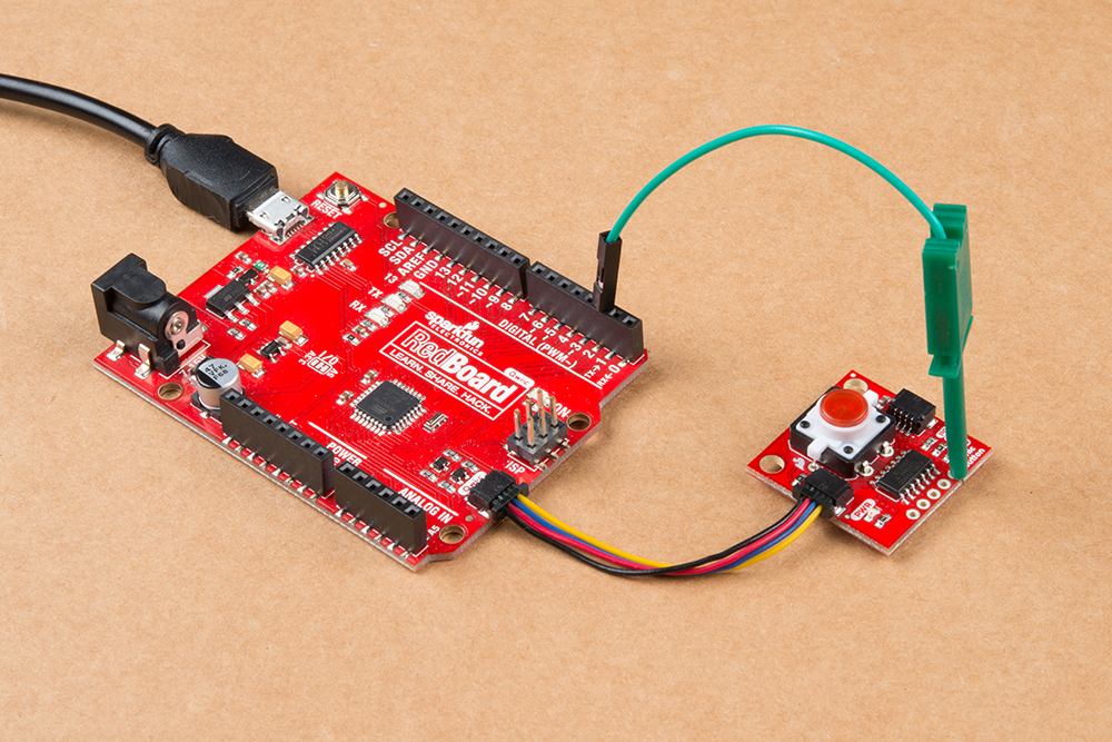
Example8_ExtInterrupt demonstrates how to use the external interrupt pin to trigger an event on an attached microcontroller. You will want to solder to the INT pin and connect it to an interrupt-capable pin. If you just need to quickly prototype a circuit using the INT pin on the Qwiic Button, you can connect to it using something like these IC Hooks. The photo below demonstrates how to use the IC Hook for a temporary connection.
The code initializes the Qwiic Button on the I2C bus, attaches an interrupt to the selected pin (D2 by default), and configures the interrupt function for any button event (pressed or clicked). The INT pin will go LOW whenever a button event is registered and the selected interrupt pin on the microcontroller will fire whenever it sees a FALLING edge (going from HIGH to LOW). If you want to see it in action, you could attach an LED to the selected interrupt pin or you can modify the code to toggle all sorts of functions whenever the interrupt pin goes LOW.
int interruptPin = 2; call to the appropriate I/O pin.