SparkFun Qwiic GPIO Hookup Guide
 El Duderino,
  Englandsaurus
Hardware Overview
As we mentioned in the Introduction, the Qwiic GPIO features the TCA9534 I/O Expander to communicate with up to eight digital input/output pins via I2C. In this section we'll examine the characteristics of the TCA9534 as well as the features of the Qwiic GPIO breakout.
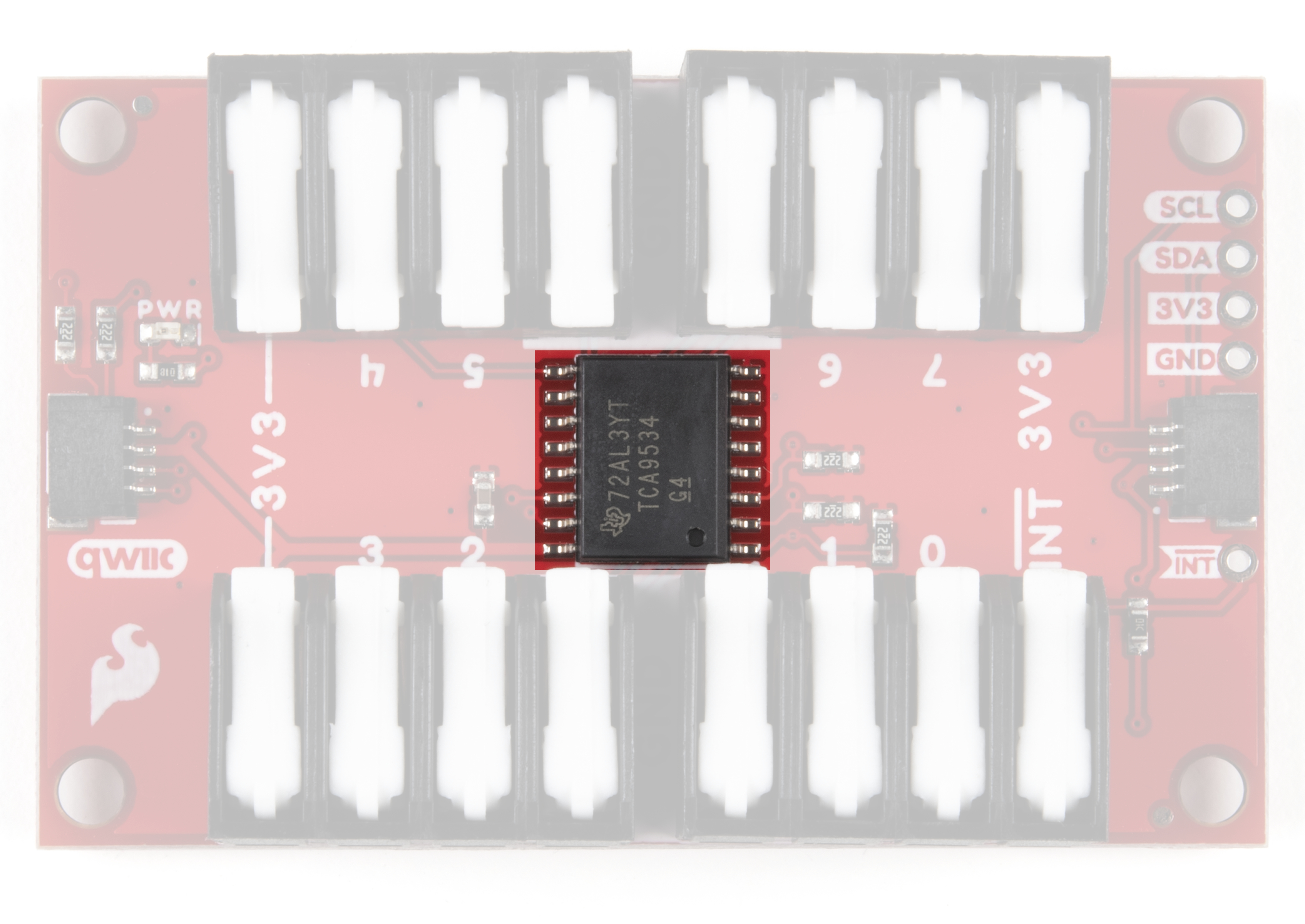
TCA9534 I/O Expander IC
The TCA9534 from Texas Instruments provides an I2C to parallel digital input output interface. We'll cover the basics here but for a thorough overview of the TCA9534 refer to the datasheet. The IC has an operating input voltage range of 1.65V to 5.5V but we recommend powering it with 3.3V via either the Qwiic connector or through any of the 3.3V and Ground pins to maintain compatibility with other Qwiic devices.
The TCA9534 supports both standard (100kHz) and fast mode (400kHz) I2C frequencies. The IC also features an active-low interrupt pin that is activated when any pins configured as an input have a different state from the Input Port register state. This means you can connect this INT pin to an interrupt-capable pin on your microcontroller to passively monitor devices connected to the TCA9534. For more information on this functionality, refer to section 8.3.2 in the TCA9534 datasheet and Example 4 - Interrupt in the Qwiic GPIO Arduino Library.
Three hardware pins (A0, A1 and A2) are dedicated I2C address select pins. We've added three jumpers to the Qwiic GPIO to allow users to have up to 8 boards on the same bus. The Solder Jumpers section below goes into more detail on how those pins and jumpers are used on the Qwiic GPIO.
Latch Terminals
The Qwiic GPIO breaks out all eight of the TCA9534's I/O pins, the interrupt pin, as well as several power rail pins (3.3V and Ground) to four 4-pin latch terminals so wiring peripherals to the board is extremely easy. All you need to do is insert a stripped wire into your preferred terminal opening and press down firmly on the latch handle to secure the wire into place.

Each I/O pin defaults as an input at power on. Sending the appropriate commands will switch them to an output and you can also invert the polarity of each pin as well via I2C. Read on to the Qwiic GPIO Arduino Library and Python package sections for more information on how to configure and interact with these pins.
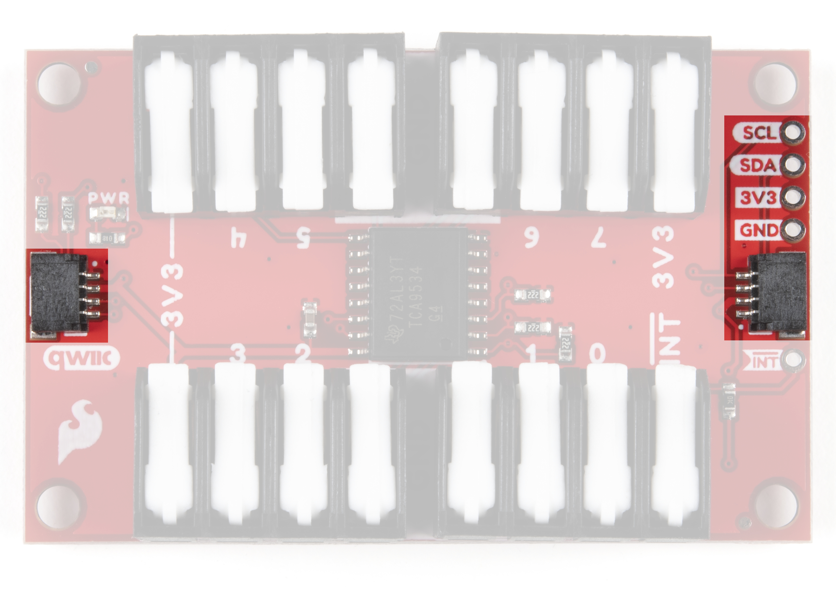
Qwiic and I2C Interface
As you have come to expect with Qwiic boards, the connections for the I2C bus (SDA, SCL, GND and 3.3V) on the Qwiic GPIO are broken out to a pair of Qwiic connectors as well as standard 0.1" spaced PTH pins for those who would prefer to solder to them. The default I2C address for the Qwiic GPIO is 0x27.
Solder Jumpers
The Qwiic GPIO has six solder jumpers to configure the board labeled I2C, PWR, INT, A0, A1 and A2. This section covers what each jumper's functionality is and how to configure them.

I2C Jumper
This jumper ties the SDA and SCL lines to 3.3V via two 4.7kΩ resistors. The default state is closed. To disable the pull-up resistors, simply sever the traces in between the pads to open the jumper. If you have multiple Qwiic GPIO's or other I2C devices on the same bus, disable all but one pair of pull-up resistors to avoid creating too strong of a resistance on the SDA and SCL lines.
Power Jumper
This jumper controls voltage to the power LED on the board. It ties the anode of the power LED to 3.3V via a 1kΩ resistor. The default state is closed. To disable the power LED, open the jumper by severing the trace between the two pads. Disabling the power LED will help reduce overall current consumption of the board.
Interrupt Jumper
This jumper ties the TCA9534's interrupt pin to 3.3V via a 10kΩ resistor and its default state is closed. This holds the Interrupt pin HIGH so it can be driven LOW when an interrupt event is monitored by the TCA9534. Open the jumper if you have another pullup on the Interrupt pin.
Address Jumpers
The three address jumpers on the Qwiic GPIO: ADR0, ADR1 and ADR2, set the I2C address of the TCA9534 by pulling them either to 3.3V or 0V/Ground. The default state of all three jumpers is closed and they tie each address pin to 3.3V via a 2.2kΩ resistor. This configuration sets the default I2C address to 0x27. By opening or closing these jumpers you can alter the address of the TCA9534 so you can have up to eight of these boards on a single I2C bus. Click the button to open the table below showing the various jumper configurations and what I2C address each configuration sets:
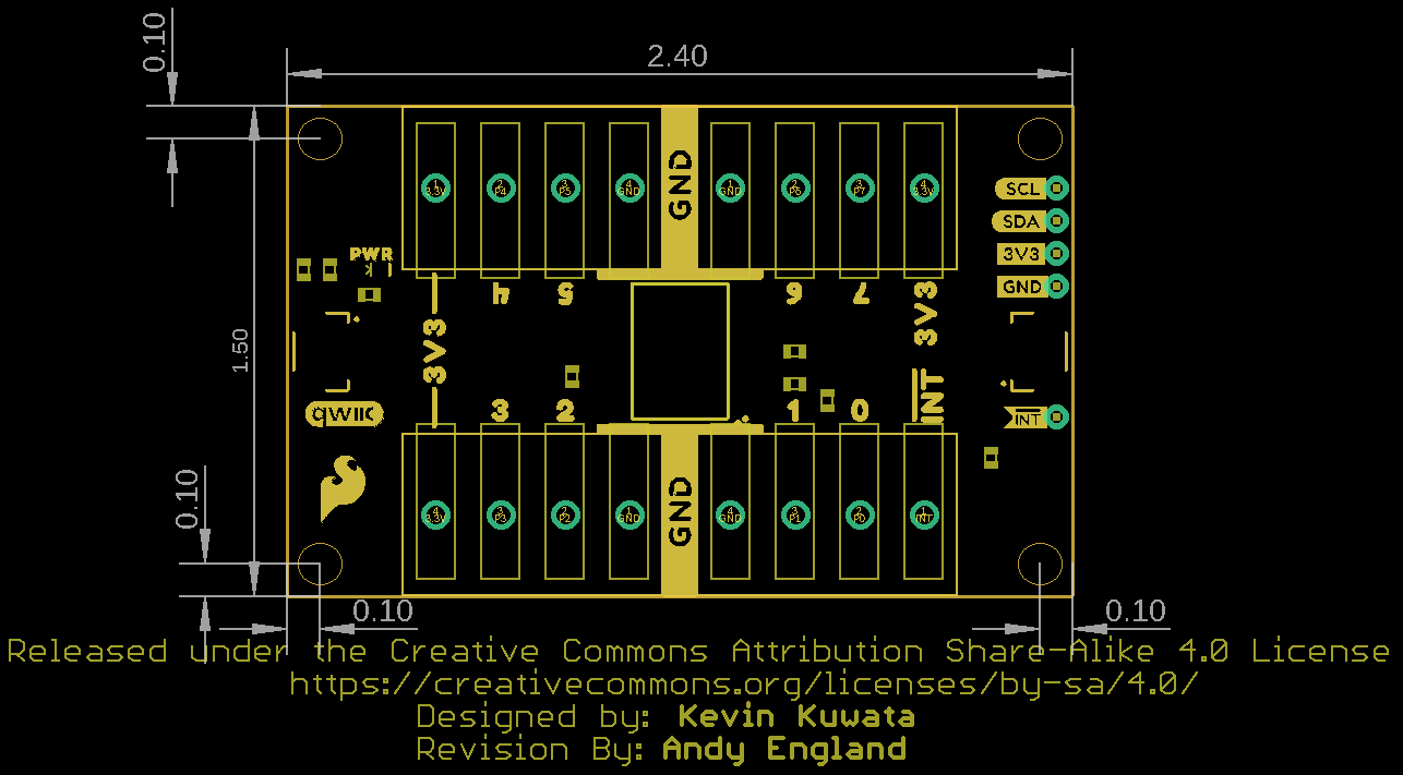
Board Dimensions
The Qwiic GPIO is a bit larger than our standard Qwiic breakout size (1" x 1"). It measures in at 2.40" x 1.50" (60.96mm x 38.10mm) and has four mounting holes that fit a 4-40 screw.
Now that we are more familiar with the hardware present on the Qwiic GPIO it's time to hook it up to our microcontroller and attach some peripherals to the I/O pins. Next up we'll detail how to assemble the board and your Qwiic GPIO circuit.