SparkFun Qwiic Quad Solid State Relay Kit Hookup Guide
 El Duderino,
  Englandsaurus
Hardware Assembly
While the Qwiic Quad Solid State Relay does not require any soldering, there is some minor assembly needed prior to using your board. In this section we'll provide a brief set of instructions to assemble your board and afterward you can start switching some high power loads.

Preparation and Initial Relay Assembly
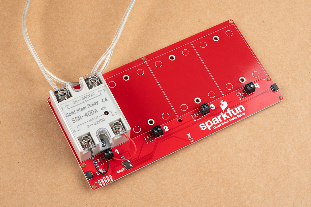
First, we want to attach our SSR's to the Qwiic Quad Solid Relay board. All you need here is a screwdriver, the screws included with the kit and your relays. Place one of the relays in the area outlined on the PCB and secure it in place from the opposite side of the PCB. Make sure the relays are oriented properly with the side labeled Input closest to the screw terminals.

Next, locate the lengths of wire included with your kit as we'll need them to connect our relays to their respective screw terminal block. Cut each wire into four even lengths and strip away a small portion of the insulation on each end. With everything unpowered, take one of your prepared wires, secure one end to the terminal labeled "-" and the other to the terminal on your relay labeled "4/-". Next, take another of your wires and secure one end to the terminal labeled "+" and the other to the terminal on your relay labeled "3/+".

For the purpose of this tutorial we're only fully assembling one of the included SSR's but feel free to attach the other three at this point.
Relay Output Load Assembly
Next up we'll want to prepare our AC load we are controlling with the relays.
You'll have to cut and strip your load AC line (usually black or red) and connect one end of the cut wire to the terminal on your relay labeled 1 and the other end to the terminal labeled 2.
If you need tips or help on safety and insulation for high voltage circuits, check out the notes about Safety and Insulation from our Beefcake Relay Control Kit.
Connecting to Microcontroller
Now that your Quad SSR Kit is fully assembled and connected to your load you can connect it to your development board using a Qwiic cable or adapter cable. If you would prefer to not use the Qwiic connectors, you can connect to the 0.1" header pins broken out on the bottom left of the board.

If you decide to use the PTH pins broken out on the board you will need to solder to them. If you are not familiar with through-hole soldering take a look at this tutorial:
How to Solder: Through-Hole Soldering
September 19, 2013
With the Qwiic Quad SSR Kit assembled and connected to your microcontroller it's time to get some code uploaded and start taking measurements!