SparkFun RTK Surveyor Hookup Guide
 Nate, Ell C
Hardware Overview - Advanced Features
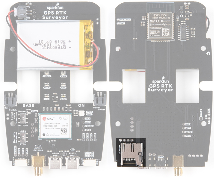
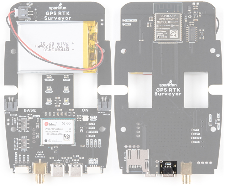
The RTK Surveyor is a hacker’s delight. Under the hood of the RTK Surveyor is an ESP32 WROOM connected to a ZED-F9P as well as some peripheral hardware (LiPo fuel gauge, microSD, etc). It is programmed in Arduino and can be tailored by the end user to fit their needs.
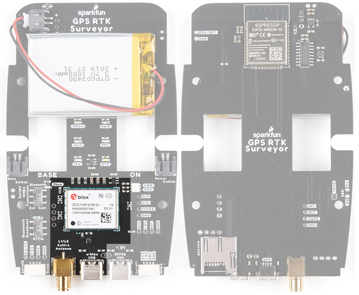
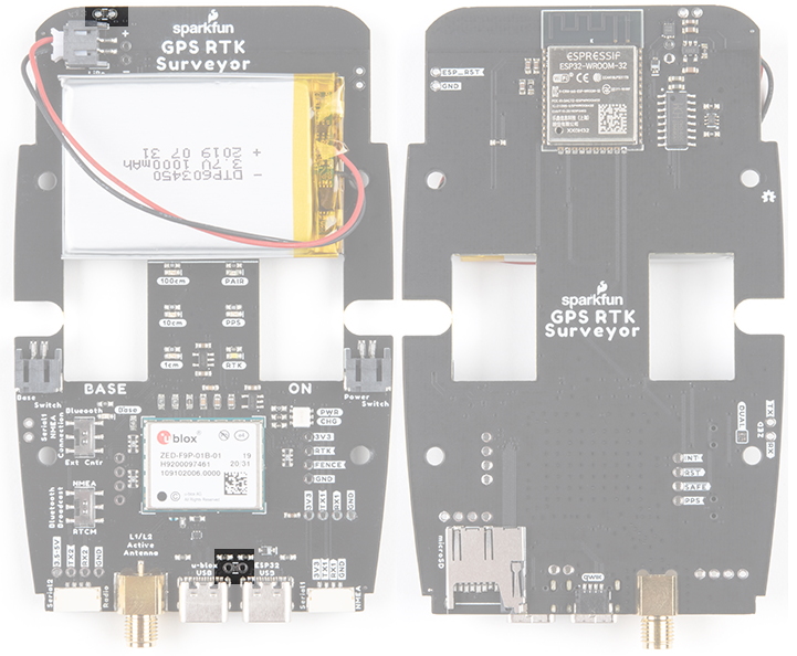
ZED-F9P GNSS Receiver
The ZED-F9P GNSS receiver is configured over I2C and uses two UARTs to output NMEA (UART1) and input/output RTCM (UART2).
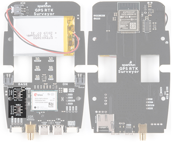
Two internal slide switches control the flow of NMEA and RTCM traffic between the external connectors and the internal BT UART used on the ESP32. Ostensibly the Bluetooth Broadcast switch can be set to pipe RTCM data to the ESP32’s UART (instead of NMEA) so that correction data can be transmitted over Bluetooth. Point to point Bluetooth radio support is not supported because the useful range of Bluetooth is too short for most RTK applications but may be helpful in some advanced applications.
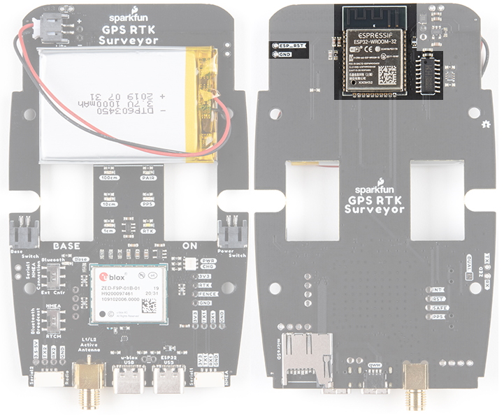
ESP32
The ESP32 uses a standard USB to serial conversion IC (CH340) to program the device. You can use the ESP32 core for Arduino or Espressif’s IoT Development Framework (IDF).
The CH340 automatically resets and puts the ESP32 into bootload mode as needed. However, the reset pin of the ESP32 is brought out to an external 2-pin 0.1” footprint if an external reset button is needed.
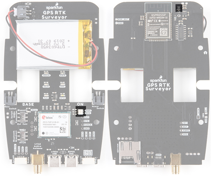
Measurement Jumpers
To facilitate the measurement of run, charge, and quiescent currents, two measurement jumpers are included. These are normally closed jumpers combined with a 2-pin 0.1” footprint. To take a measurement, cut the jumper and install a 2-pin header and use banana to IC hook cables to a DMM.
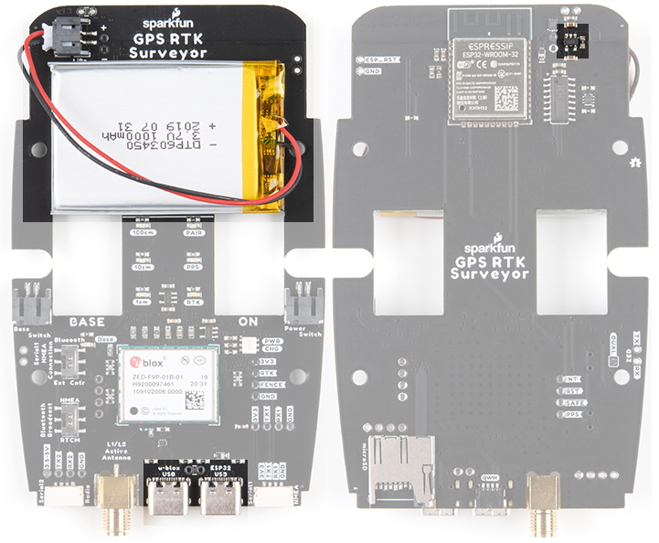
LiPo and Charging
The RTK Surveyor houses a standard 1000mAh 3.7V LiPo. The charge circuit is set to 1A so with an appropriate power source, charging an empty battery should take roughly one hour. USB C on the RTK Surveyor is configured for 2A draw so if the user attaches to a USB 3.0 port, the charge circuit should operate near the 1A max. If a user attaches to a USB 2.0 port, the charge circuit will operate at 500mA.
MAX17048 Fuel Gauge
The MAX17048 is a simple to use fuel gauge IC that gives the user a statement of charge (SOC) that is basically a 0 to 100% report. The MAX17048 has a sophisticated algorithm to figure out what the SOC is based on cell voltage that is beyond the scope of this tutorial but for our purposes, allows us to control the color of the power LED.
Qwiic
A Qwiic connector is exposed on the end of the unit. This allows connection to the I2C bus on the ESP32. Currently the stock RTK Surveyor does not support any additional Qwiic sensors or display but users may add support for their own application.
microSD
A microSD socket is situated on the ESP32 SPI bus. Any microSD up to 32GB is supported. RTK Surveyor supports RAWX and NMEA logging to the SD card. Max logging time can also be set (default is 10 hours) to avoid multi-gigabyte text files. For more information about RAWX and doing PPP please see this tutorial.