SparkFun SAMD21 Pro RF Hookup Guide
 Elias The Sparkiest
Hardware Overview
If this is your first time with the SAMD21 then check out our great write up on the hardware specifications of the SAMD21AG MCU and see how it compares with an ATmega328P.
SAMD21 Mini/Dev Breakout Hookup Guide
November 12, 2015
Let's move onto the SAMD21 Pro RF and its hardware features.
Supplying Power
You can power the SAMD21 Pro RF in a number of external 5V sources. At the head of the board, you'll see a micro-B USB connector and a lithium polymer battery connector that will take any of our stocked LiPo battery options. To safely charge, we recommend using a LiPo with a capacity that is higher than 500mAh. Note the two plated through holes just to the right of the LiPo connector that can be utilized for direct soldering of a LiPo Battery. Next to the switch, you'll see the pins labeled RAW for a external source of 6V or below.
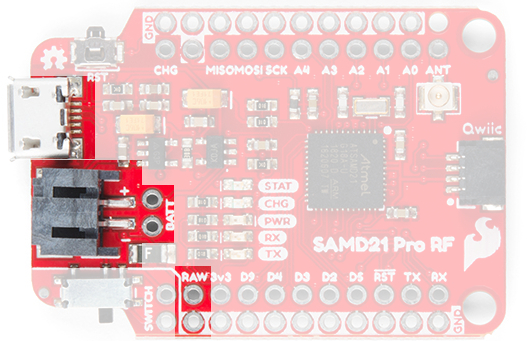
Warning: Powering the SAMD21 Pro RF is easy but the onboard low noise, low dropout voltage regulator can not handle anything above 6V. Please be attentive with how you power it.
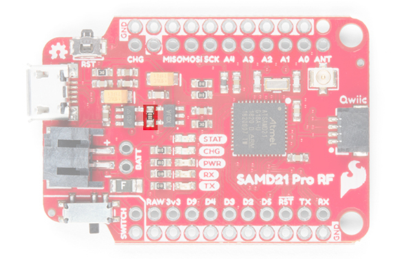
Oops! We accidentally tied the VDDCORE pin to VCC (3.3V); instead of ground via a capacitor (see the SAMD21 datasheet). This issue doesn't affect the overall functionality of the board; however, for low power applications, it does increase the amount of current drawn.
For experienced users that are comfortable with their skills to make the required changes, the board can be modified to resolve this issue. Unfortunately, due to the complexity of the modification we will not be providing instructions, as users can easily damage the board permanently with the VDD pad right next to the VDDCORE pad. (*Experienced users with the required skills, should be able to determine and make the necessary changes on their own, without further assistance.)
Update: We have updated the board to fix this issue. Therefore, only users who have the previous version without the SWD lines broken out are affected.
Updated version with VDDCORE fix. All other boards are affected by this issue.
Power Switch
On the side of the board, there is a power switch. When the switch is flipped toward the PTH pads, power is provided to the board from either the USB connector or LiPo battery. When the switch is flipped away, power is removed from the 3.3V voltage regulator. In case you forget, the back of the board has labels indicating what position is ON or OFF.
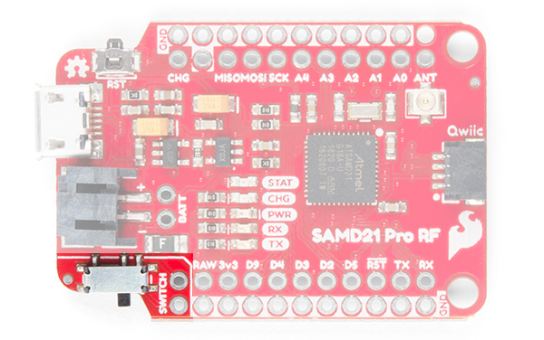
Adjacent to the power switch are also PTH pads. These are included for those that are interested in inserting the board in an enclosure and want to add an external button or switch. The PTH pad closest to the inside of the board connects to the voltage from the USB connector and LiPo battery. The PTH pad closest to the outside (next to the GND rail) connects to the 3.3V voltage regulator.
Pinout
Logic Levels: Keep in mind that this is a 3.3V system, which interfaces nicely with our Qwiic environment and other 3.3V devices. If you are using the SAMD21 Pro RF with your external 5V devices, we recommend adding a level shifter in between.
Below is a table with every pin on the SparkFun SAMD21 Pro RF and it's function.
| Pin | Description |
|---|---|
| RAW | Input Supply Voltage should never exceed 6V |
| GND | Ground on outside thru-holes |
| 3v3 | 3.3V OUT |
| RST | 3.3V OUT |
| D2, D3, D4, D5, D9 | Digital I/O Pins |
| A0, A1, A2, A3, A4 | Analog I/O Pins |
| RX/TX | Serial Ports |
| MOSI/MISO/SCK | SPI |
| ANT | Antennae for RFM Module |
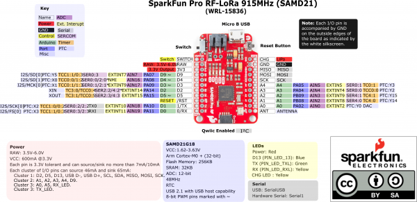
For reference of the pins and other characteristics, we also have the graphical datasheet below.
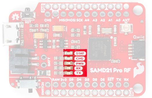
LEDs
This product carries the full gamut of LEDs we've come to expect on SparkFun development boards: STAT LED, CHARGE LED, RX/TX indicators, and a Power LED. The STAT LED is on pin 13, typical on most Arduino boards. The RX and TX LEDs indicate activity on the USB serial port and are also available through the Arduino IDE using the macros PIN_LED_RXL and PIN_LED_TXL as your pin declarations. These LEDs are active-low, so writing the pin HIGH will turn the LED off. The charge LED is controlled by the onboard MCP73831 and lights up when a battery is being charged and turns off when the battery is full.
Note:In the latest revision of the SAMD21 Pro RF, we have broken out an LED jumper for low power applications. The LED jumper disables only the power LED, but the power savings are quite significant. For the other LEDs:
- The STAT LED is tied to pin 13, so users can just avoid using that pin.
- The RX and TX LEDs are only powered during serial communication.
- The CHG LED is only powered during charging of a connected battery, but at that point users probably won't be worrying about a few mA when there is a power supply.
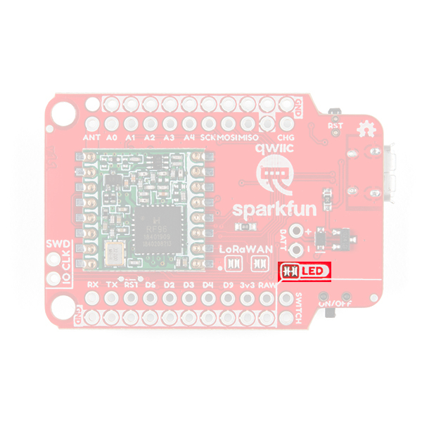
Jumper for power LED.
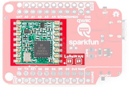
RFM95W Radio Module
The RFM95W Radio Module is a powerful but low power module that allows for point to point radio communication. It also has the capability of utilizing the Long Range Wide Area Network (LoRaWan) by closing two LoRaWAN labeled jumpers on the underside.
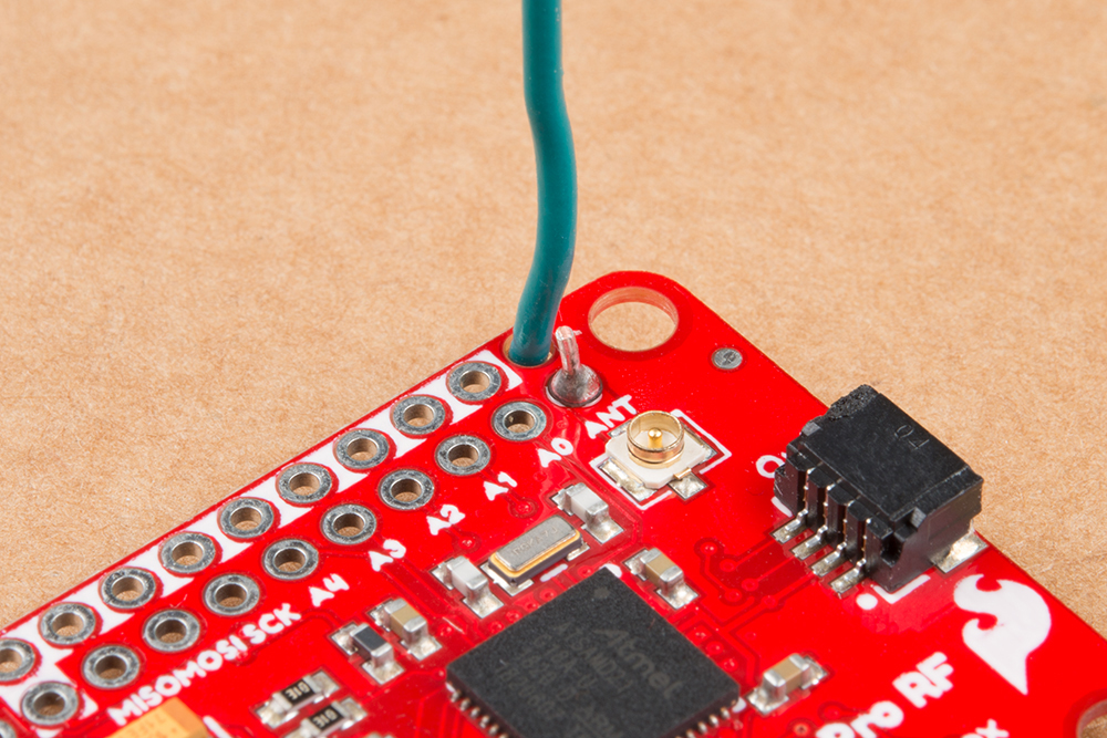
Antenna
There are two options for an antenna on the SAMD21 Pro RF, a wire and a u.FL connector. The plated through hole and the connector are both labeled by the same ANT silk on the topside of the product.

When using the through hole for your antenna, notice the unplated hole just above it. The purpose of this hole is to thread the wire antenna through it so that it takes the stress of daily wear and tear off of the solder joint. Woot!
How Much Wire Length Do I Need?
We have you covered, here are wire lengths for quarter-wave antennas at 915MHz and 868MHz:
| Country | Frequency | Length (inches) | Length (mm) |
| Americas | 915 MHz | 3.07" (3 + 1/16") | 78mm |
| Europe | 868 MHz | 3.38" (3 + 3/8") | 86mm |
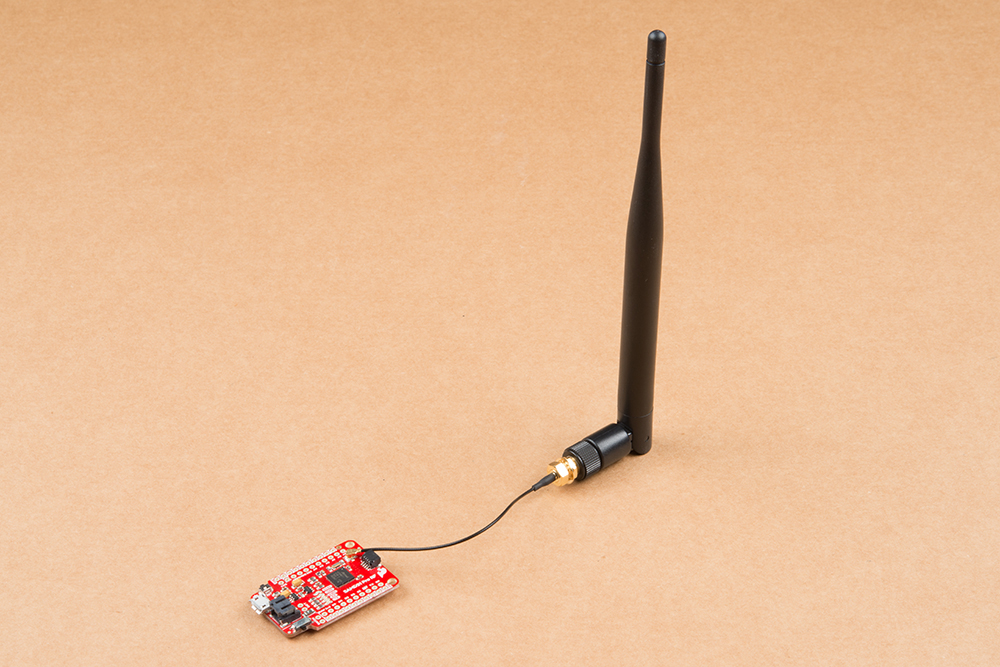
u.FL Antenna
Another option is to connect a LoRa Antenna to the u.FL connector. The image below uses the 915MHz antenna. Make sure to select the appropriate antenna for your region.
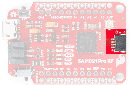
Qwiic Connector
On the tail end of the product is a Qwiic connector. If you are not familiar with the system, you can get a full rundown here. In short the Qwiic system is an I2C environment of products that can be rapidly prototyped because we've broken out the I2C lines: ground, power, clock, and data, to a four pin JST connector. There's no need for solder or a soldering iron and our catalog of products with a Qwiic connector are growing rapidly.
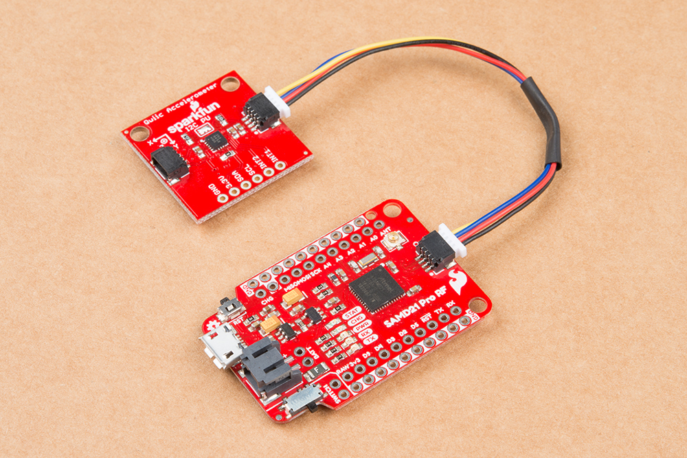
Here the SAMD21 ProRF is connected to the Qwiic Triple Axis Accelerometer.
SWD Pins
In the latest revision of the SAMD21 Pro RF, we have added some PTH pins for software debug (SWD). These pins will primarily be used by more advanced users. For more information on the SWD, users should check out the ARM Programming tutorial.
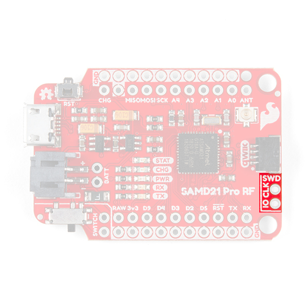
IO and clock pins for SWD.
Hardware Limitations and Current Capabilities
This topic is mentioned in detail under the SAMD21 Dev/Mini Breakout Hookup Guide but it's worth restating again here. Depending on the task it's given, the SAMD21's core will usually consume between 3-17mA. There should be plenty of juice left from the 600mA 3.3V regulator to power other sensors or components off the board's 3.3V supply rail.
Each I/O pin can sink up to 10mA and source up to 7mA, with one caveat: each cluster of I/O is limited to sourcing 14mA or sinking 19.5mA. The GPIO clusters are:
| Cluster | GPIO | Cluster Supply (Pin) | Cluster Ground (Pin) |
|---|---|---|---|
| 1 | SWCLK, SWDIO | VDDIN (44) | GND (42) |
| 2 | 30, 31 (USB_HOST_EN, TX_LED) | VDDIN (44) VDDIO (36) | GND (42) GND (35) |
| 3 | D2, D5, D6, D7, D10, D11, D12, D13, D38 SCL, SDA, MISO, SCK, MOSI (USB_D-, USB_D+) | VDDIO (36) VDDIO (17) | GND (35) GND (18) |
| 4 | D0, D1, D3, D4 | VDDIO (17) | GND (18) |
| 5 | A1, A2, A3, A4 D8, D9 | VDDANA (6) | GNDANA (5) |
| 6 | A0, A5, AREF (RX_LED, RTC1, RTC2) | VDDANA (6) | GNDANA (5) |
If for example, you're sourcing current to four LEDs tied to pins 0, 1, 3, and 4 (cluster 4), the sum of that current must be less than 14mA (~3.5mA per LED). On a related note, Cluster 3 is mostly occupied by the Radio's various inputs: interrupt, chip select, and reset as well as the Qwiic Connector.