SparkFun Troubleshooting Tips
 bboyho
 Introduction
"It's not working!" A common utterance made when working with electronics. But, have no fear. There are numerous troubleshooting tips that make diagnosing your problem much simpler than it may seem. In this tutorial, we will be exploring a few general troubleshooting tips and possible solutions that frequently come up in SparkFun's Technical Support department. Some of these tips may not apply to all cases and projects, but it is a good place to start to determine the source of the problem.
Assumptions
The development and breakout boards that are produced by SparkFun are usually tested on a pogobed and inspected by a technician for quality control before they are packaged and sent out. Let's assume that the boards are good to start.
Constant Innovation in Quality Control
Suggested Tool
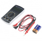
At a minimum, a low cost multimeter is a must for basic troubleshooting. Depending your setup, you may need additional tools and components.
Suggested Reading
If you aren't familiar with the following concepts, we recommend checking out some of these skill tutorials. The complexity of the project may require additional skills to help you troubleshoot.
How to Solder: Through-Hole Soldering
How to Use a Breadboard
How to Read a Schematic
Serial Terminal Basics
How to Use a Multimeter
Start Something
"I want to connect 10,080 addressable LEDs attached to a network of wireless modules and controlled by one board attached to a shark. Oh, and I have not worked with electronics before."
Whoa, whoa, whoa. Let's take a giant step back and start simple before going crazy with a project. Also, please leave any animals out of the project! Our technical support department receives some interesting cases. The above example is a generalization of the questions that we get in support. Before we even dive into a project, let's begin with the basics and where to look for information to get started. You will want to start by checking out any associated documents. Dream big, but start with these small steps.
Start at the Product Page and Kits
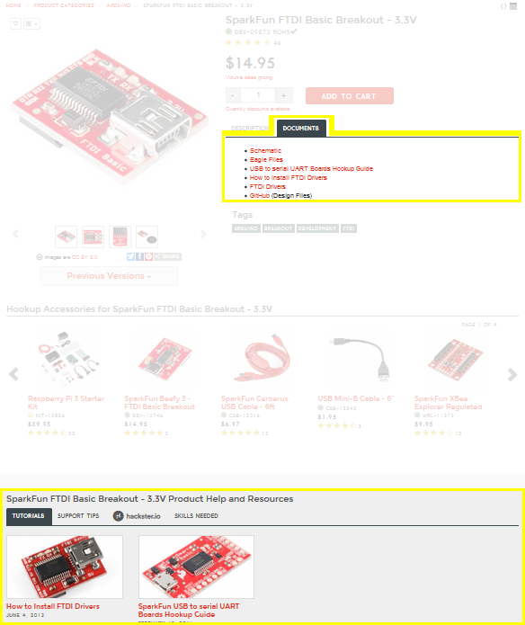
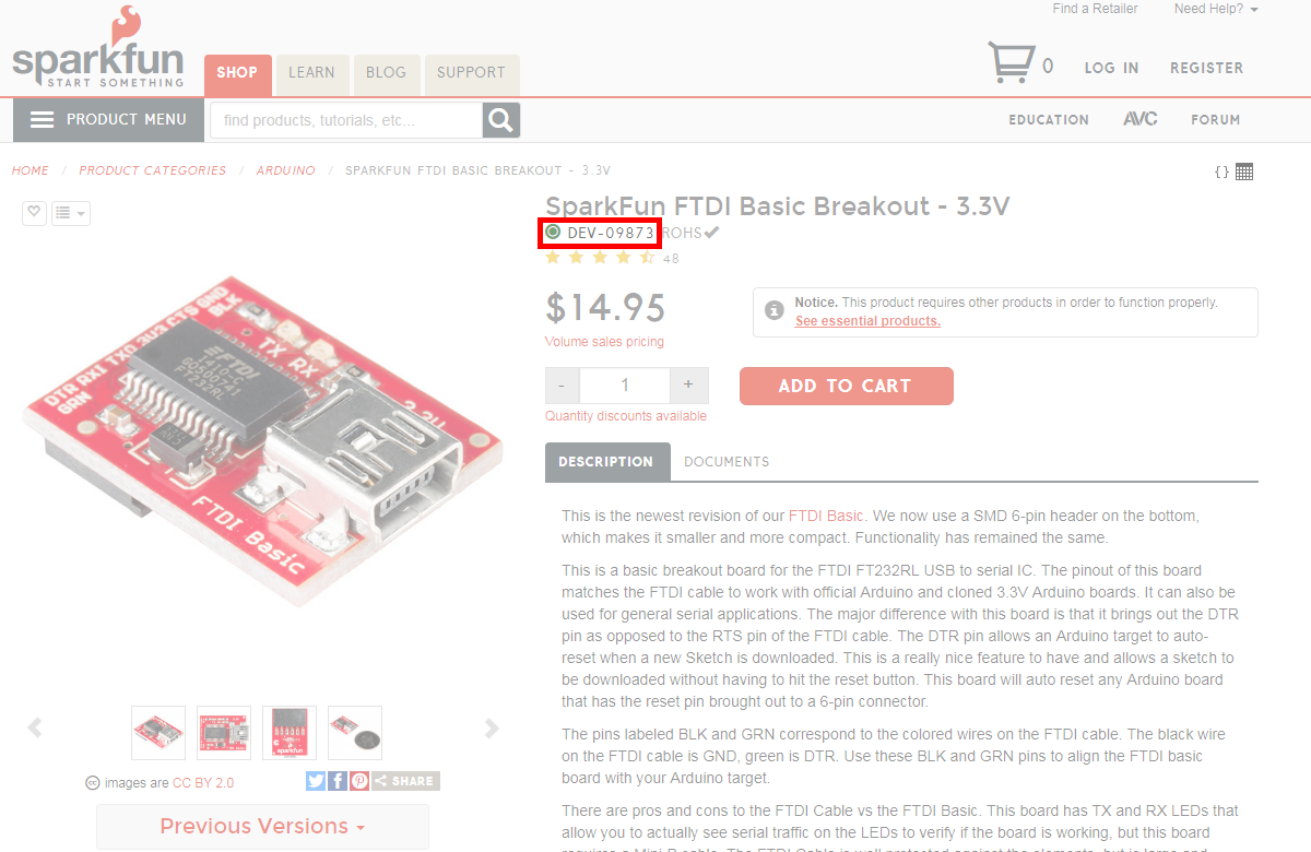
We at SparkFun try our best to provide information about the parts sold in our catalog. Besides reading the product description, try checking out a product page's document section for resources. Depending on the product, there can be a number of useful links. Let's take a look at the SparkFun FTDI Basic Breakout --- 3.3V! The information linked on the product page can range from:
- Schematics
- Eagle Design Files
- Hookup and Experimental Guides
- Project Tutorials
- Drivers
- Datasheets
- User Manuals
- GitHub Repositories
If you scroll down past the recommended products, "Product Help and Resources" may show up if there is information linked to the product. These can range from tutorials to technical support tips to projects that the part has been used in under Hackster.io. Farther down at the bottom (not shown in this image), you will also notice a section for comments provided by users.
You can also check out the specific development boards used in kits to get started. There are basic examples and projects within each of these kits to help you get started with the product. If you have not worked with hardware electronics or programming before, you might want to check out the SparkFun Inventor's Kit V3.3 for RedBoard or micro:bit. These kits do not require you to solder components together.
Datasheets and Manuals
Depending on the complexity of the board, there can be a lot of components on the PCB with different specs. We usually try to think about the main IC on the breakout board and look at the Absolute Maximum Ratings for the I/O pins, how much the chip can handle overall, and what the IC is able to do. Try looking at our previous tutorial on How to Read a Datasheet for tips on reading a datasheet. User manuals can also provide examples and application notes on how to use the product.

Online Research for Resources
Besides browsing at SparkFun's growing list of online tutorials, YouTube videos and blog posts (i.e., Enginursdays, Engineering Roundtable, etc.), there are several other resources online. Here a few that might be of use:
- Non-SparkFun Manufactured Parts
- Instructables
- Hackster.io
- Electronics Stack Exchange
- Forums (i.e., SparkFun, Arduino.cc, Raspberry Pi, etc.)
The cloud knows all...that is posted on the internet. Besides using the local search engine at the top of the page, try using an online search engine with different search queries to see if anyone has done something similar to what you are doing. Chances are, there is someone in the world who has done the project (or something similar) already, and they have provided some documentation online.
Hardware Checks
So you have followed the instructions, and the part or project does not work as expected. You even tried to do exactly what the hookup guide and tutorial told you to do! Part of working with electronics and programming is diagnosing the problem and finding a remedy to get the part to function. Don't worry; it happens to the best of us, and challenges only help us learn and grow. Let's try to find out what may be going on in your circuit!
Check Your Connections
Is the part or project connecting? Let's clarify what it means to "check your connections." A common method of troubleshooting is to check your hardware connections and power for physical problems.
• Is there continuity between the pins, and is the connection secure?
Any loose connections can cause problems because it will cause your circuit to be incomplete. It is best to double-check wired connections just in case a wire was connected incorrectly or is loose. The images below show poor electrical connections for prototyping due to the thin wires being inserted into a breadboard and female header sockets. Any bumps and vibrations applied to the circuit can cause the circuit to lose its connection.
 |
 |
 |
The small wires connected to the breadboard may become loose depending on how it was manufactured and how much wear was applied to the metal strip. The thin wires connected in the female headers are worse due to the tolerance of the socket.
For a more secure connection, it would be better to solder the wires to header pins and add heat shrink. You can also make an adapter using the SparkFun snappable protoboard or make a custom shield using any of the prototyping boards.
• Are there shorts?
Shorts in your circuit can cause problems if there is a pin touching something that it is not supposed to. Make sure that components are not getting extremely hot to the touch. If pins are shorting, remove power and check to see if a loose wire is touching something that it should not. Make sure the board is not on top of a metal table.
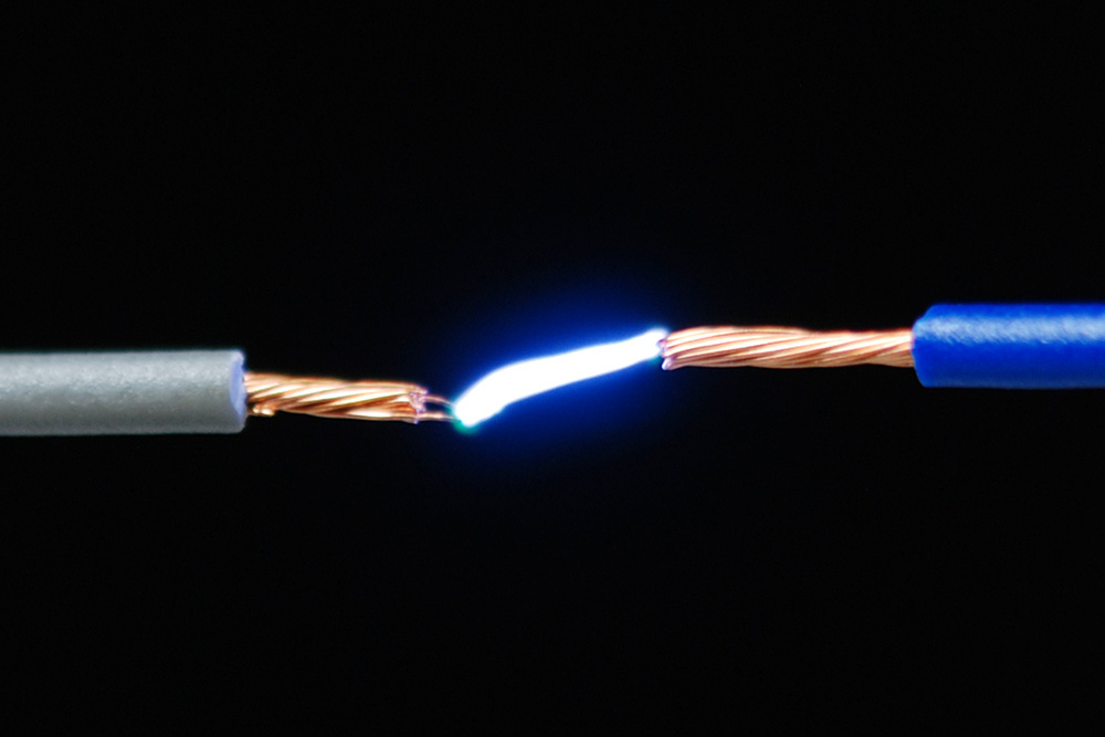
• Is the wire or cable bad?
Sometimes a wire or cable is bad, causing the circuit to not connect. You can try checking the circuit with a multimeter set to measure continuity. Otherwise, try using a different wire or cable.
• Where did you get the USB cable from?
Certain cables are designed to be charging cables, so there might not be any data lines connected in the USB cable. Also, there might be internal micro tears in the cables. We recommend checking and using a different USB cable. We had an instance where a customer was using USB cables from his school's lab to upload code to an Arduino. Three out of the four cables were bad because they were damaged. The fourth cable worked with his device. You might want to try ordering a brand-new USB cable if that is the case.
• Was the component connected using the correct polarity?
Certain components have a certain polarity and will only function when it is connected in the correct position. Make sure that the component is populated correctly. This can range from batteries, integrated circuits, microcontrollers, transistors, voltage regulators, electrolytic capacitors, diodes. For more information, check out our tutorial on polarity.
Polarity
June 14, 2013
• Did you use the basic hookup?
If everything appears to be wired correctly, you might want to try going back to the beginning and looking at the basic hookup. Also, disconnecting the parts and rewiring each circuit can help troubleshoot. This will assist in narrowing down the problem.
Keep in mind that two parts may be named similarly or look the same, but in reality they are not. For example, while an Arduino Mega 2560 has the name Arduino in it, it may not be a direct replacement for a circuit that uses an Arduino Uno R3. There are a few subtle differences that some may not be aware of (i.e., different pin locations, limitations in Software Serial, board definition, etc). Sometimes you may need to redefine a pin or rewire the circuit to get it working as expected.
Make sure that you are grabbing the correct part from your parts bin by double-checking the IC's label. As an example, the TMP36 is not the same as a BJT transistor. While the package appears to be the same, they are different! This is common in our SparkFun Inventor's Kit. In another case, a customer had used a different n-channel mosfet. While the n-channel mosfet looked the same, the specs were different, causing the transistor to not fully turn on in the circuit.
Check Your Solder Joints
• Are your solder joints ideal and making a sufficient connection?
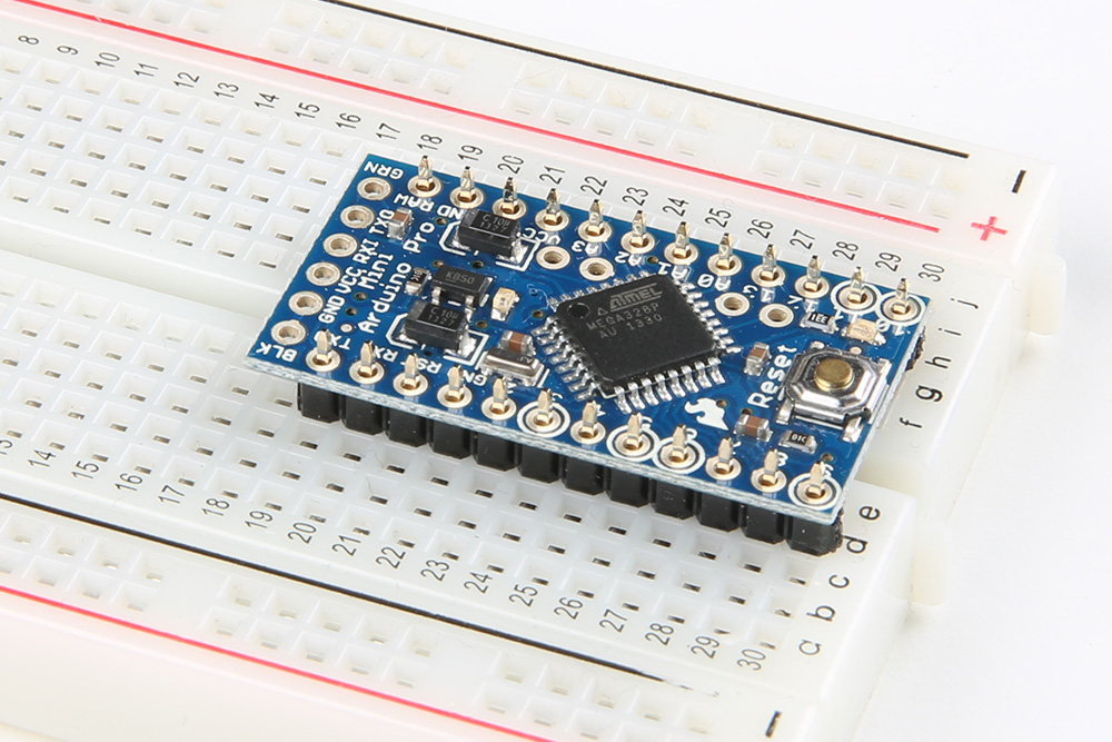
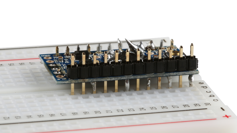
Ah yes, we check the connections once again. If you are trying to connect a breakout board on a breadboard using wires, you will want to make sure that the connection between the breakout board and the wire is sufficient. The three images shown below are not ideal solder joints.
In the first image, there are no solder joints connecting the header pins to the breadboard. This is a great idea if you need help soldering header pins, but not if you are trying to connect the Pro Mini to other breakout boards.
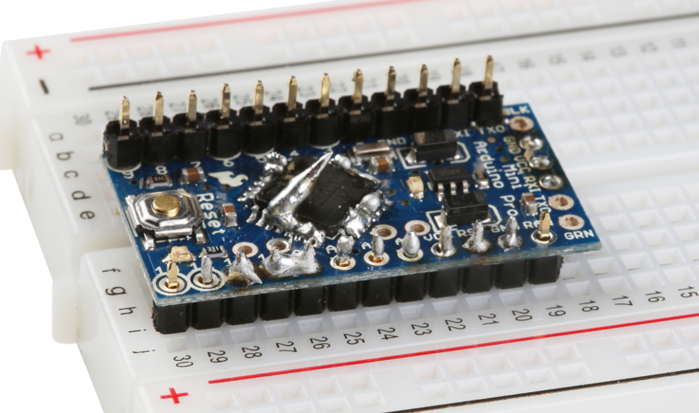
The second image might have solder, but the joints are not ideal. The first pin along row 30 has no solder. The pin on row 29 has some solder on the header, but there is no contact with the board. The pin on row 28 is OK, but it has too much solder on it. Some of the solder blob is also extending from the pin. The pins on row 27 and 26 have an unintentional solder jumper. The pin on row 25 may have solder on the through-hole pad and pin, but it is not connecting. The only pin that seems to have an ideal solder joint is the RST pin on row 21. We would want to rework all the other pins by reheating the pins or adding more solder to make sure the pins have a sufficient solder joint. Additionally, there are unintentional solder jumpers connecting between pins on the Atmega328P IC. To remove unintentional solder jumpers, try using a solder wick and checking out the next question.
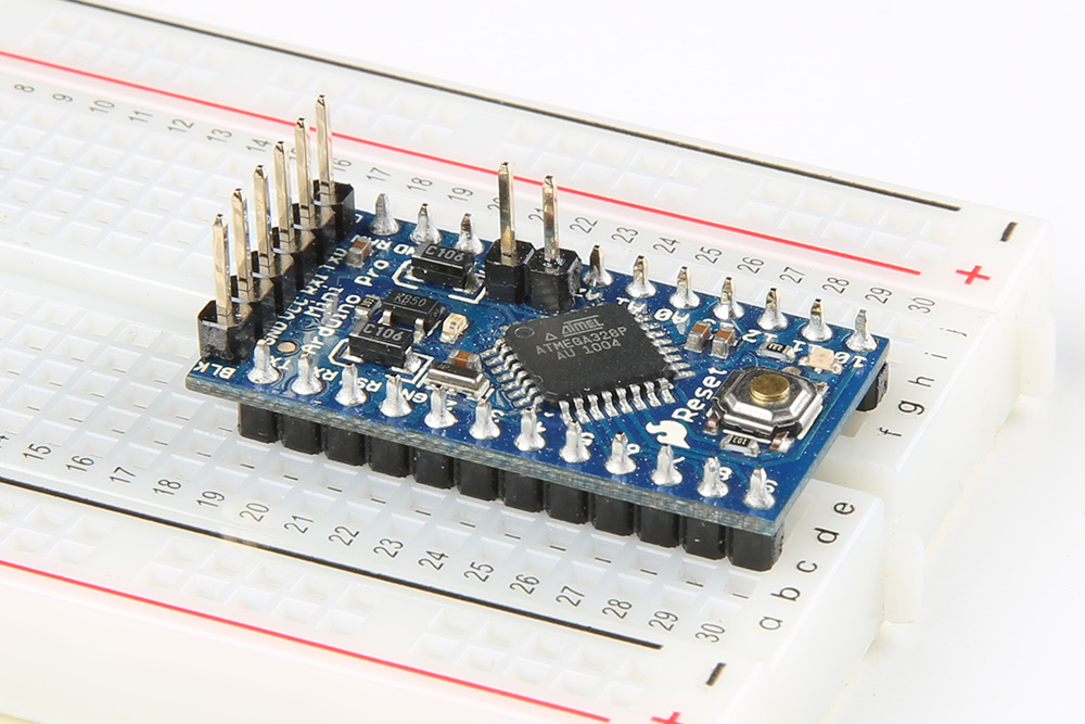
The third image clearly shows the 1x12 header incorrectly soldered on the Pro Mini. Solder should be applied with the shorter side of the header. The black housing holding the pin should be between the PCB and the breadboard. Additionally, the solder joints are extending the length of the pins. The Pro Mini is not able to be fully inserted into a breadboard due to the length of the straight header pins.
The solution would be to add solder or rework the solder joints for a secure connection. The image below has ideal solder joints on the Pro Mini. For more information about soldering and ideal solder joints, check out our tutorial for through-hole soldering.
• Are there solder jumpers connecting pins where they should?
Depending on the circuit, you may want to have a solder jumper on a certain part of the board. If there are unintentional solder jumpers on the IC or header pins, the solution would be to rework the board and remove the solder jumper.
Below is an example of a solder joint that was not intentional for the "Simon Says" PTH Soldering Kit.
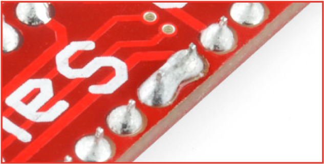
To fix, you could grab a solder wick to remove the solder jumper. For more information on how to use a solder wick, try checking out the Troubleshooting section here labeled "Solder Jumpers."
• Is there water-soluble flux residue on the boards?
If you are using water-soluble flux, you want to make sure to remove any water soluble flux residue that is left on the board. This is to prevent pin oxidation and temporary shorts between pins caused by dendrites. Below is an image of water-soluble flux residue left on a production panel.
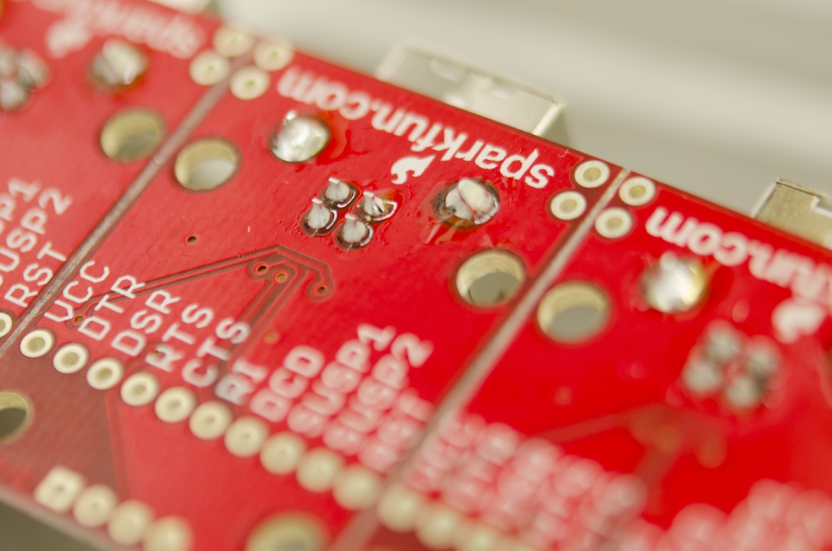
While some circuits may work fine with the flux left in place, we have seen dirty boards wreak havoc on boards that are sending a signal through a serial UART (i.e., uploading code to an Arduino or sending an ASCII character to another UART) or I2C. It is better to avoid any issues caused by water-soluble flux left on the board. In fact, the SparkFun boards that we assembled are washed if they use this type of flux!
To remove water-soluble flux residue, you can use a little deionized water or isopropyl alcohol and a toothbrush. Alternatives to deionized water may be to use non-mineral bottled water first before tap water for hobby use. However, deposits from tap water could form and cause problems in the future. Using compressed air, you would dry the board to remove any excess flux residue or water that is on the board. Hot air from a heat gun or rework station can also be used to dry the board.
Certain components are sensitive to water, so you should be careful about getting these components wet. Here is a short list of components that should avoid contact with water:
- Character LCDs
- 7-Segment LED Displays
- Batteries
- GPS Modules
- Wireless Modules
- Barometric Pressure Sensors
- Slide Potentiometers
- Microphones
- Speakers
- Heart Rate Monitor ICs
If water gets trapped in them and you power the board, it will probably damage the component.
Length of Wire
• Are you using extra long wires?
Depending on the conducting material that you are using, the resistance of conductive thread and wires can increase over a certain distance. This is more apparent with conductive thread and the solution may be to double your thread.
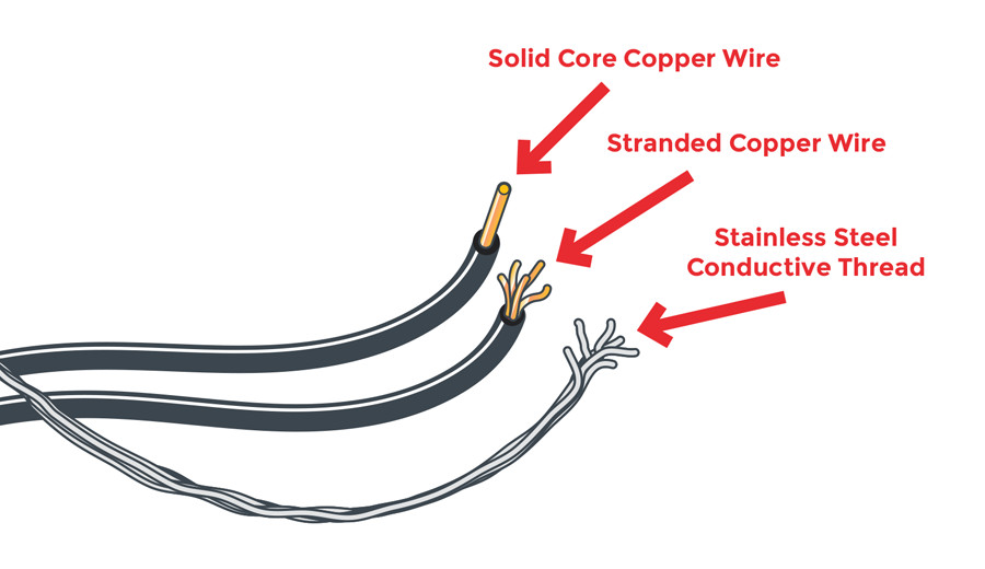
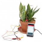
If you are using wire over a distance of more than a few hundred feet, you may also notice issues. For example, there have been a few cases where an I2C sensor was not working properly after a certain length. Since I2C was designed to work over a short distance, sensors can have issues sending data when used over a certain number of feet. The solution may be to adjust the pull-up resistors or be clever in sending data (i.e., using a microcontroller for each sensor node and adding a wireless device).
Check Another Computer
• Have you tried using a different computer?
We recommend checking with another computer to see if the device can work. We've had issues where a device was not working on a customer's laptop but was working on his/her computer. There was something with the settings of the computer that was preventing them from using the device properly.
• Is there a problem with the USB Hub or USB port that you are using?
Try connecting directly to a USB port instead of through a USB hub. The device might not be getting enough power or might not be communicating correctly. Also, there can be issues with using some USB-to-serial converters with USB 3.0. Try testing on a different computer. In some instances, customers were able to get it working on a USB 2.0 hub when the device was not working with a USB 3.0 port.
Check Your Logic Levels
• Can I connect a 3.3V sensor to a 5V board?
Not all boards use the same voltage for logic levels. For example, the RedBoard Programmed with Arduino and the Arduino Uno R3 use 5V logic. However, if you move to other boards like the ESP8266, SAMD21, Arduino Due or Raspberry Pi, the I/O pins are not 5V tolerant. Make sure the logic levels match or are tolerant with whatever device you are connecting to the development board.
If the signal only needs to be converted down, you could use three 10k ohm resistors to build a voltage divider. For signals being sent both directions, you could use a logic level converter (i.e., Bi-Directional Logic Level Converter, PCA9306 Level Translator, TXB0104 Voltage Level Translator, etc.) to communicate safely. For more information about logic levels, try checking out the tutorial below.
Stacking Multiple Boards
• Are you stacking more than one board (i.e., Arduino Shield, Raspberry Pi HAT, Beaglebone Cape, etc.) together on top of your development board?
It may be possible to stack boards together, but that depends on the pins each board is using. Try checking out the board's design files, schematic and basic example code to determine what pins are being used for each shield. You may need to reroute pins, redefine pins or change the serial addresses (i.e., I2C, SPI) in the code when stacking multiple board together with a development board. When using multiple boards, you will need to combine example code to get it working in the project.
Check Your Location for Interference
• Is the component not working in a room or building?
Is there magic in the air or ghosts in your electronics? Maybe. Or you can just try using the board in a different location. This is common among GPS receivers if you are using it inside a building. To avoid GPS lock problems, try using the GPS receiver closer to the perimeter of the building, outside, in a different location to avoid surrounding buildings, or using an external antenna that extends outside.
We've also seen problems with ultrasonic sensors when used in certain parts of our building. For example, the HC-SR04 ultrasonic sensor would work fine in one location of the building, but we noticed that the HVAC's acoustic noise was tuned just enough to interfere with the sensor. To avoid this noise, we had to use the sensor in a different part of the building.
Using a magnetometer and seeing abnormal readings? This might be caused by hard and soft irons in the environment. Try looking at this old tutorial from our retired 9DOF Razor to find more about hard and soft irons.
Check Your Power
• Is your power supply sufficient enough?
Make sure that you have a power supply that is able to provide the power that your system needs. For example, if you are lighting up three WS2812B addressable LEDs with an Arduino, a 5V/1A power supply would be sufficient. However, this is a different story if you are lighting up two or more 5M addressable LED strips. For such large installations, you would need a beefy power supply for long lengths and probably need to add power between each 5M segment.
If a power supply is not able to provide enough power, your microcontroller or single-board computer may brown out. As another example, the Raspberry Pi 3 consumes just a bit more current compared to its previous models. While the previous 5V/2A power supplies worked for the earlier generations of the Raspberry Pi, a 5.1V/2.5A power supply is needed to power the Pi 3 sufficiently.
• Why does my Arduino stop working every time my motor starts up?
Try checking your power supply. It's possible that the motors are causing a dip in voltage and causing the microcontroller to brown out. It is usually suggested to have an external power supply connected to the motors to prevent brownouts and resetting the microcontroller. Make sure to connect the GND to the rest of the system for reference. You could also use a beefier power supply that is able to provide enough power for both the motor and microcontroller.
• Why does my project work with a power supply connected to a wall outlet but not with a 9V battery?
Depending on the battery chemistry and the manufacturer of the battery, the discharge rate may be different from a power supply that is connected to a wall outlet. The internal resistance is higher for 9V batteries compared with other battery types. Also, the internal resistance varies among manufacturers. Therefore, it is not an ideal source for high-current applications. You may want to consider using other battery chemistries to power the project.
Power Cycle
• My project was working fine when connected to the wall outlet for a few months, but it is now not working as expected.
Try power cycling the project by removing power and powering the circuit back up. If there is a reset button, you may be able to just hit that button. You may need to unplug the power supply from the wall outlet, disconnect the power Vin, wait a few seconds, reconnect the power supply to Vin, and insert the power supply back into the wall outlet. Try testing the wall adapter with a multimeter to see if it is still outputting power or plugging a known good lamp into the wall outlet.
Heat Dissipation
• Is it normal that my motor driver is getting hot to the touch?
Heat dissipation is normal when using a motor driver and motor. Depending on how hard the driver IC is being pushed and the power supply being used, you may need a heatsink to achieve the full potential of the motor driver. Such breakout boards are usually designed to help with some heat dissipation. In addition to adding a heatsink, there are methods of dealing with heat.
Electrostatic Discharge (ESD)
• Did you ground yourself before touching the device?
Certain devices are sensitive to static electricity. When moving around, a person can build up static electricity and discharge it through the board. It can be worse during the winter when walking over carpet. Make sure to touch a metal cabinet to ground yourself. While some boards can handle a few minor shocks, the IC can be damaged after a certain point.
Limitations of the Product
• Are you using the component as expected?
When a product is released to the wild, it might not be used as intended. For example, usually you think of LEDs as emitting light. However, it is possible to use a microcontroller and LED to detect light.
Now don't expect all components to be able to do what they are not intended to do. For example, the XBee Series 1 transceiver may be able to transmit data wirelessly, but do not expect it to be able to stream video reliably like a WiFi dongle. The specifications (i.e., data rate) are different.
Wireless
• Why won't my wireless device connect to the wireless network?
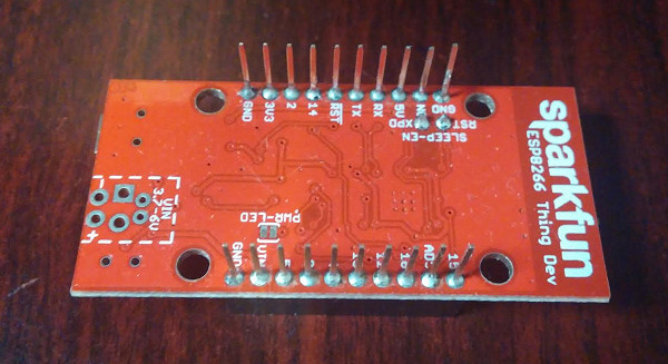
Try checking to see if you are using the correct WiFi network name and password. It is possible that the credentials were entered incorrectly. The example codes provided with WiFi-enabled devices (like the SparkFun ESP8266 Thing Development Board) require you to manually enter the network name and password.
Just like checking another computer, you may want to try testing the WiFi-enabled device on another WiFi network. Using a WiFi-enabled device can be a problem if you are using the device in a school network. Due to a school's configuration, you may need to contact your local IT department that manages the wireless network to allow the device to connect. It also may be possible that the wireless router is damaged or not compatible with the wireless-enabled device.
• Why won't my wireless device work inside of a metal enclosure?
Placing a wireless device inside a metal enclosure (i.e., a Faraday cage) essentially limits and can block any electromagnetic fields. Signals being sent or received will not be able to be transmitted. Try using an external antenna so that the transceiver is able to extend outside of the metal enclosure.
Software Checks
There are many languages out there. For the scope of this tutorial and troubleshooting, we are going to focus on the Arduino IDE (Integrated Development Environment) and common problems when uploading code to an Arduino development board. However, some of these tips may be useful when troubleshooting in other development environments.
FTDI Drivers
• Did you install the FTDI drivers?
If you have not uploaded to an Arduino that uses an FTDI before or connected an FTDI to your computer, you need to make sure that you have installed the latest FTDI drivers. Try looking at the tutorial listed below for installing the driver for your operating system. The tutorial is based off of FTDI's instructions. For more in-depth guidance, try looking at FTDI's Installation Guides.
How to Install FTDI Drivers
June 4, 2013
Keep in mind that device drivers can vary depending on the USB-to-serial converter populated on the development board. If you are using a different chip, you will need to install the respective drivers. Here are a few other drivers:
For more information about different drivers, check out this blog post.
• How do I know if I have drivers installed?
With the device is plugged in, you can see a few COM ports when you select Tools > Serial Port in the Arduino IDE's menu. When you unplug the device and reopen Tools > Serial Port, you might see a COM port disappear. By process of elimination, you can see what COM port it has enumerated to. You can also see this when you open your device manager checking the Ports (COM & LPT) tree.
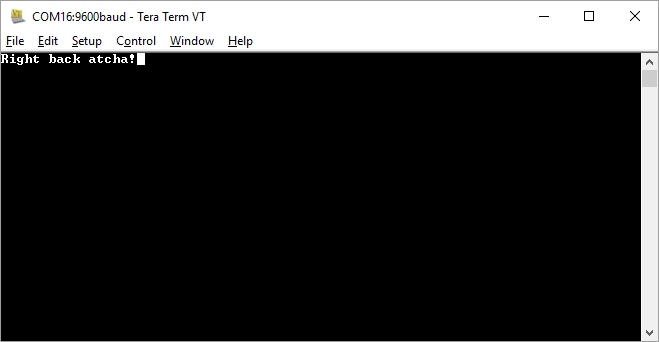
• How do I know if my USB-to-serial converter is sending serial data?
To verify that the FTDI or any USB-to-serial converter is working, you could do a serial loop back test or echo test. In order to perform this test, you would connect a jumper wire between the UART pins Rx and Tx.
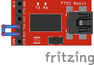
Open a serial terminal (like Tera Term) with the setting 9600 baud, 8-none-1-none. By typing into the serial terminal, any characters sent using a keyboard will be echoed back on the screen. You should also see the Rx and Tx status LEDs indicating when data is being sent.
Arduino IDE Versions
• Is there something wrong with my Arduino IDE?
There are improvements and benefits with each version release of the Arduino IDE. However, there can be unforeseen bugs and differences in the way that code is compiled. If there are warnings in the error output, usually you can ignore them. If you are having issues compiling, sometimes you need to uninstall and reinstall the Arduino IDE on a computer. You can also try deleting certain Arduino files.
If the Arduino-based development board does not require a certain IDE version, you can try rolling back and using a lower version of the Arduino IDE (like v1.6.5). Rolling back and testing with a stable/working IDE may be the solution until the next release.
Board Selection
• Did you select the correct board definition?
If you did not select the correct board definition, you will not able to upload code. Check the Arduino's associated documentation for more information on the correct board selection. You can find a list of Arduino board definitions in the Tools > Board selection menu.
• Why am I not able to see my Arduino board in the board selection menu?
There can be some issues with the Arduino IDE v1.6+ due to the different file structure requirements. This may cause an Arduino board to not show up in the default list.
The latest SparkFun Arduino-compatible board updates can be found on the SparkFun Arduino board add-on GitHub repository. This repository contains support for SparkFun's Arduino-compatible development boards and instructions on how to install the board add-ons:
If you tried installing the latest board and code is still not compiling, you may want to roll back to a previous version of the board add-on. If there was more than one board version released, you should be able to click on the board in the board manager and see a small dropdown menu for different versions.
COM Port Selection
• Did you select the correct COM port?
You need to make sure that you are selecting the correct COM port in your Tools > Serial Port menu. With the device plugged in, you can see a few COM ports when you select Tools > Serial Port in the Arduino IDE's menu. When you unplug the device and reopen Tools > Serial Port, you might see a COM port disappear. By process of elimination, you can see what COM port it has enumerated to. You can also see this when you open your device manager checking the Ports (COM & LPT) tree.
Installed Arduino Libraries
• Does your example code require libraries to be installed?
If you don't install the libraries, Arduino won't understand certain functions because they were not defined for it. You will usually be able to see example code try to include it near the top of the sketch file. I recommend looking at this tutorial to properly install the libraries.
Installing an Arduino Library
January 11, 2013
• I installed the necessary Arduino libraries, so why is it still not compiling?
Try reinstalling the Arduino IDE. There was one case when one of our engineers uninstalled and reinstalled the Arduino IDE when he had problems with a library. Otherwise, you may want to reinstall the Arduino library. Sometimes the library downloaded is corrupt or accidentally installed wrong, so you would need to reinstall the Arduino library.
Corrupt Bootloader or Bricked Arduino
• How do I recover my Arduino if the bootloader is corrupt?
If you have another Arduino microcontroller or an AVR programmer, you could reinstall the bootloader. The tutorial listed below was written for an Arduino Uno with ATmega328P. If you are using a different AVR microcontroller or Arduino-compatible board, you may need to select a different board definition to burn its bootloader.
Installing an Arduino Bootloader
December 4, 2013
• My Arduino with ATmega32U4 stopped working after uploading new code. What happened to my ATmega32U4-based microcontroller?
Most likely the wrong board definition was selected when uploading code, or something is interfering with the register that handles COM port communication. There is a way to recover the ATmega32U4-based Arduino using the double reset method. You may need an AVR programmer as a last resort. Try checking out the comment here for links to more in-depth tips on recovering ATmega32U4s with different bootloaders.
Semantics Error and Debugging
• Why is my code not working even though it compiles?
This sounds like a pretty general question, but it's likely a semantic error. While the code is able to compile and is free from syntax errors, the code might not be written to do what you intended. Assuming the hardware connections and boards are good, it is possible that:
- A pin or variable was not initialized correctly.
- A variable was not calculated and saved correctly.
- The wrong variable is printing to the Serial Monitor.
- You are using values outside of an array[].
- There is a baud rate mismatch.
- A
delay()function is preventing a certain line from executing fast enough. - The sequence of code is not executed properly.
The list of reasons why this may be happening can go on depending on the complexity of the project. The simplest method of debugging can be turning on an LED when we reach a certain part of the code. However, the best method of troubleshooting Arduino code is to try to step through using the serial.print() function to debug. If used correctly, the function is more flexible and can indicate that we have entered a line of code.
Maybe you want to print "I entered this function" to the Serial Monitor after pressing a button or when a sensor reaches a certain value. The serial.print() function can also be used to inspect variables in order to know what to expect from a sensor's output range. The function can also be used to verify calculations. Other environments allow you to step through the code to simulate what may happen without the need for serial.print().
SparkFun Troubleshooting Checklist
Regardless of our level of experience, failure rates can be reduced and issues can sometimes be resolved faster by having a checklist. Here is a list of questions to ask yourself when troubleshooting your project:
Hardware Checks
Check Your Connections
▢ Is there continuity between the pins, and is the connection secure?
▢ Are there shorts?
▢ Is the wire or cable bad?
▢ Where did you get the USB cable?
▢ Was the component connected using the correct polarity?
▢ Did you use the basic hookup?
▢ Are your solder joints ideal and making a sufficient connection?
▢ Are there solder jumpers connecting pins where they should?
▢ Is there water-soluble flux residue on the boards?
Length of Wire
▢ Are you using extra long wires?
▢ Have you tried using a different computer?
▢ Is there a problem with the USB Hub or USB port that you are using?
Check Your Logic Levels
▢ Can you connect a 3.3V sensor to a 5V board?
Stacking Multiple Boards
▢ Are you stacking more than one board (e.g., Arduino shield, Raspberry Pi HAT, Beaglebone Cape, etc.) together on top of your development board?
Check Your Location for Interference
▢ Is the component not working in a particular room or building?
Power Supply
▢ Is your power supply sufficient?
▢ Does your Arduino stop working every time your motor starts up?
▢ Does your project work with a power supply connected to a wall outlet but not with a 9V battery?
Power Cycle
▢ Was your project working fine when connected to the wall outlet for a few months, but is now not working as expected?
Heat Dissipation
▢ Is your motor driver getting hot to the touch? Is this normal?
Electrostatic Discharge (ESD)
▢ Did you ground yourself before touching the device?
Limitations of the Product
▢ Are you using the component as expected?
Wireless
▢ Will your wireless device not connect to the wireless network?
▢ Will your wireless device not work inside of a metal enclosure?
Software Checks
FTDI Drivers
▢ Did you install the FTDI drivers?
▢ How can you tell if you have the FTDI drivers installed?
▢ How can you tell if your FTDI is sending serial data?
Arduino IDE Versions
▢ Is there something wrong with your Arduino IDE?
Board Selection
▢ Did you select the correct board definition?
COM Port Selection
▢ Did you select the correct COM port?
Installed Arduino Libraries
▢ Does your example code require libraries to be installed?
▢ You installed the necessary Arduino libraries, so why is it still not compiling?
Corrupt Bootloader or Bricked Arduino
▢ How do you recover your Arduino if the bootloader is corrupt?
▢ Your Arduino with ATmega32U4 stopped working after uploading new code. What happened to the ATmega32U4-based microcontroller?
Check, Test and Recheck
Maybe you rushed through a step. Try checking back through the troubleshooting checklist. Or maybe your assumption was wrong? Check your assumptions. While rare, it's possible that there is something on the board that is bad (e.g., tombstoned SMD components, insufficient solder or a bad PCB).
Even turning the circuit off and coming back at another time will help in troubleshooting the problem with a different approach.
Help!
Still having problems after going through the troubleshooting checklist, tests and rechecks? We find that the SparkFun forums is the best form of contact, as we can share the highest level of information and documentation with the community. When posting in the SparkFun forums, please be ready with as much information as possible. In some cases, customers were able to resolve their issues by gathering some of this information and browsing the forums:
SparkFun Part Number (i.e., SKU) --- This can be found in the invoice's list of items or on the product page.

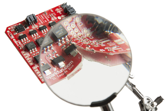
High-Quality, Clear Images of Solder Joints and Setup --- A few high-quality, clear images of the solder joints and setup will be useful. Make sure that the image is focused and there is adequate lighting. Look at the photo to verify that we can see the circuit before submitting.
Below shows a poor image of the setup, where it is hard to see what is going on. That candy bar does look appealing, though.
The image below shows a clear picture of the solder joints that can help us troubleshoot.
The image below shows a clear image of the setup and pin connections. While the wires are cut off, we should be able to follow the connections. However, it may be a problem when troubleshooting if there is more than one wire with the same color.
Information About Your Setup --- This can include the power supply's voltage and current settings, if the board was powered, modifications to the board, additional parts connected to the system, or your environment.
Once you have this information ready, try posting on the forums!
Resources and Going Further
Check out some of SparkFun's resources below:
Want more information on troubleshooting? Check out these related blog post.