SparkPunk Hookup Guide
 Byron J.
How It Works
How To Play The SparkPunk
The SparkPunk is a very simple synthesizer, using the common arrangement of oscillators that feed a filter.
The basic recipe for playing it is to press the button, and operate the controls. Listen to the results, and adjust to taste. Explore and have fun. Some people are drawn to mellow, soothing sounds, while others prefer clangourous tones. With all of the controls, you should be able to explore both ends of the spectrum.
In order to apply the SparkPunk more meaningfully, it helps to understand what's inside, and how the switches and pots control it.
Block Diagram

The block diagram above illustrates the major functional blocks of the SparkPunk. Following things from left to right, we first see the trigger pushbutton. It is connected to the oscillators, which are allowed to run when the button is pressed - otherwise they are silent. The output of each oscillator is translated an octave lower by the sub-octave generators. The oscillator waveforms and suboctaves can be selected using the switches, which mix them together, before reaching the bandpass filter. Finally, the signal goes to the volume control and output buffer amplifiers, which allow the SparkPunk to drive small speakers or headphones.
We'll cover how each of these pieces works in more detail in the next few sections.
Theory of Operation
Oscillators
The heart of the SparkPunk is the 7556 dual timer IC. The 7556 is a CMOS replacement for the 555.
A quick digression into the history of this part: the 555 might be considered one of the classic integrated circuits - so useful and versatile that Forrest M Mims wrote a whole booklet full of 555 circuits. The 555 has a close relative in the 556, which is simply two 555's in the same package. However, the 555 and 556 draw a lot of current (leading to shorter battery life), and can introduce noise into the power supply. The 7555 and 7556 are CMOS replacements for the older chips, which draw substantially less current. Thus 555 x 2 = 556. 556 + CMOS = 7556.
The SparkPunk uses the the 7556 in a stable (free-running) mode. The circuit is from figure figure 2A of the 7555 datasheet. The resistor R has been replaced with a potentiometer series with a 470 Ohm resistor, to limit the maximum frequency when the pot is at minimum resistance.
The frequency is calculated using the formula f = 1/(1.4RC). The 7556 has two timer circuits inside, and the SparkPunk uses both, configured identically, except for the capacitor values - the first channel produces lower pitches than the second, as shown in the following table.
| Channel | Cap Value | Maximum R (Pot at CCW) | Minimum R (Pot at CW) | Minimum Frequency | Maximum Frequency |
| 1 | 1 uF | 470 | 10470 | 68 | 1519 |
| 2 | 0.47 uF | 470 | 10470 | 145 | 3233 |
The actual frequencies will vary due to component tolerances.
The circuit also makes use of the reset and control voltage inputs on the 7556.
The chip is held in reset until the pushbutton in pressed, or a voltage is present on the GATE input of the expansion port. These two voltages are combined with the diode OR gate formed by D1, D2 and R5.
The 7556 also has control voltage inputs, which are connected to the expansion port. We'll cover the expansion port in more detail on the modifications page.
Sub-Octave
The sub octave circuit is created using a T-type (toggle) flip-flop. The pulse waves from the oscillators are tied to the clock input of the CD4013 flip-flop. On every rising edge from the 7556, the flip-flop changes state. You can see this on the oscilloscope below:

Each rising edge on the top waveform causes the bottom waveform to change state, while falling edges on the top are ignored. This results in a second wave with one half the frequency of the input. This behavior is also known as "clock division."
In musical terms, halving a frequency is equivalent to dropping one octave. This yields a wave that can add richness to the original, without adding very many components - one IC is used to generate both sub-octaves. Because it tracks the input signal, it also stays in tune as the oscillator pitch changes.
Mixer
With two oscillators and two suboctaves, we have a total of four tone sources. The sources are combined using an inverting op-amp summing stage.
The switches marked P1, P2, S1, and S2 connect the signal to the summing bus, allowing for 16 different combinations of the oscillators and suboctaves.
Since the 7556 and flip-flop are logic sources, each input to the mixer is swinging between the supply rails - square waves that jump between 0V and 9V. If we were to try to combine them directly, we could wind up with a total voltage of 36V. The opamp is only capable of swinging to slightly less than the rails, so each input is attenuated by a factor of 1/10, leaving the result in the 3.6V range.
Filter
The filter is an active bridged-T topology. A passive bridged-T is a simple notch filter.
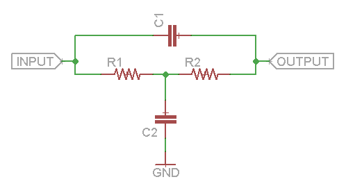
By placing that filter in the feedback loop of an op-amp, we can invert the frequency response, turning the notch into a peak.
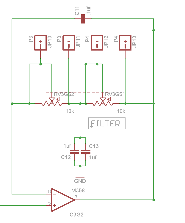
This filter topology was selected for several reasons. It doesn't take too many components, and it allows the filter to be tuned with a pair of equal value resistors, in this case a dual-gang potentiometer. Finally, the peak amplitude doesn't change as a function of frequency, which sounds cool when you turn the knob!
There is a spice file containing a number of other filter topologies in the GitHub repository, showing how some alternate filters compare.
Output Stage
The output stage is a volume control, followed by a pair of op-amp buffers, AC coupled to the output pins via the electrolytic caps C14 and C15. When stereo headphones are connected, each ear is driven by a separate amplifier. There are also connection points for an optional loudspeaker.
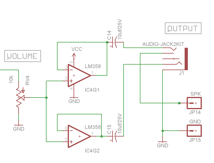
The output jack has a switching feature - it provides a default connection when nothing is plugged in, that is overridden when something is connected. On the SparkPunk, the speaker terminals are the default connection, which is broken when headphones are inserted. This means plugging in headphones silences the speaker.
Design files
The schematic and PCB artwork are in the GitHub repository.
There are also LTSpice circuit simulation files for the unit as a whole, with some of the intermediate portions in separate simulations.
Modding the SparkPunk
With this understanding of the guts of the SparkPunk, let's explore how we can modify and customize the kit.