SparkPunk Hookup Guide
 Byron J.
Modifications
The SparkPunk was designed with the idea that it can be customized, modified and extended. Your circuit bending is welcome here.
Cosmetics
Customize your SparkPunk by adding the knobs of your choice.
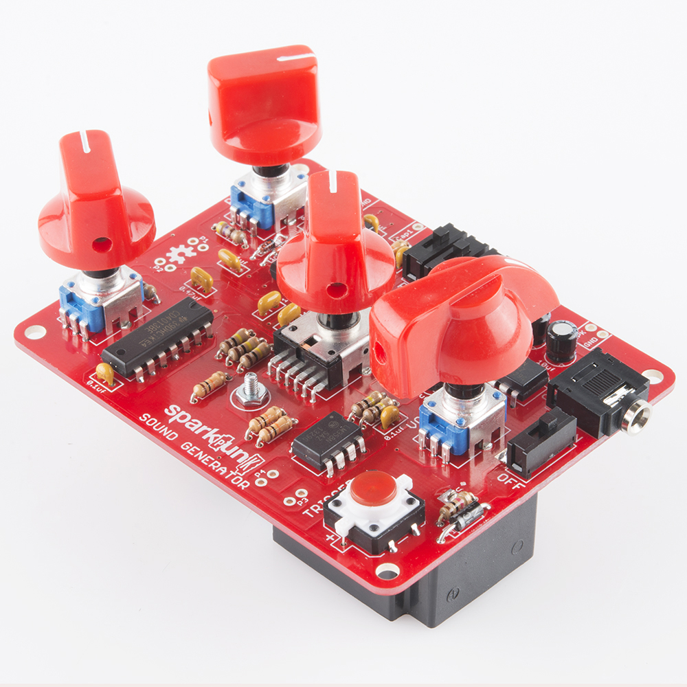
The author likes using the small red stove-type knobs for the pitch and filter controls, and a red chickenhead for the volume control. Of course, the Goes To Eleven knobs have their benefits, as well.
Once you've got knobs, you can loop rubber bands around the knobs, so you can adjust multiple parameters simultaneously. You can also cross the rubber band over in a figure-8, so that turning one knob up turns another down.
Without Adding Components
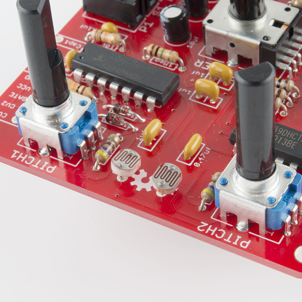
The ceramic capacitors that set the frequency of the oscillators are very temperature dependent. These are the two caps between the pitch potentiometers, near the OSHW gear logo. By simply touching them with a warm fingertip, you can cause the pitch to drift. If you start with the oscillators in tune with each other, touching one of those caps will cause them to drift, resulting in a pulsating beat-frequency effect.
As inspired by the Handmade Electronic Music book, you can explore the back of the circuit board with a damp fingertip. You'll find that some locations cause notes to spontaneously trigger, pitches to bend, or other random misbehavior.
Adding Electronic Components
External Speaker
You can solder a small speaker (such as this or this) between the terminals marked "SPK" and "GND."

As we mentioned in the How It Works section, plugging in headphones will disable the speaker, so you can enjoy your SparkPunk without disturbing others.
Photocells
There are positions on the PCB for adding photocells to the SparkPunk. Photocells are resistors that change value depending on exposure to light. In the dark they have a high value, which drops as they are illuminated. The result is that you can control the SparkPunk without touching it.
Positions P1 and P2, between the pitch potentiometers, control pitch 1 and pitch 2, respectively.
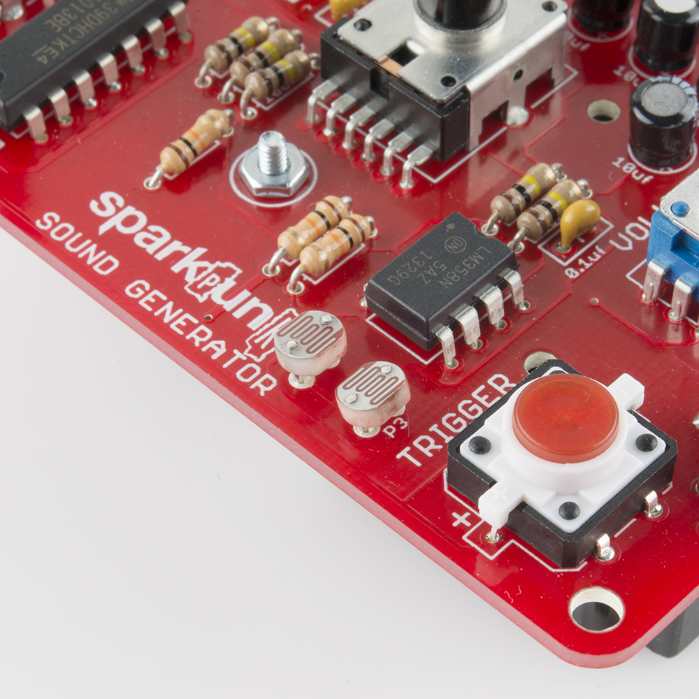
Populate P3 and P4 (near the trigger button) to make the filter cutoff frequency light-sensitive.
The photocells are in parallel with the potentiometers. The pots and photocells interact - you can experiment with how the pot rotation influences the light response of the cells.
External Input
The pad IN can be used to route external signals through the SparkPunk filter. They will be mixed with the output from the pitch and sub-octave stages.
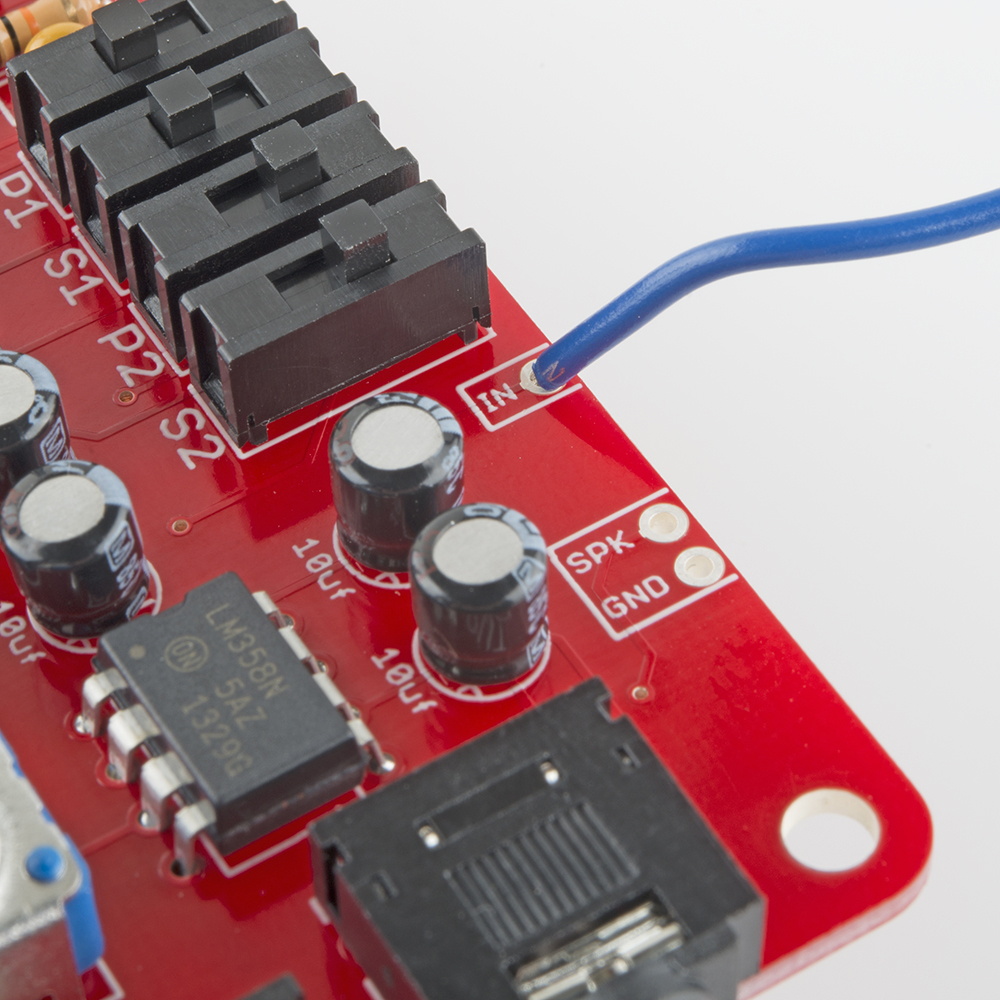
For instance, this could be used with the Gram Piano. Desolder the speaker from the Gram Piano, and run a wire from the Gram Piano's speaker "+" terminal to the IN pad on the SparkPunk. Now you can effect the piano output using the SparkPunk filter.
Cross Modulation
Connect CAP1 to CV2, then turn on P2 and/or S2. They will react in interesting ways as you adjust PITCH1 and PITCH2.
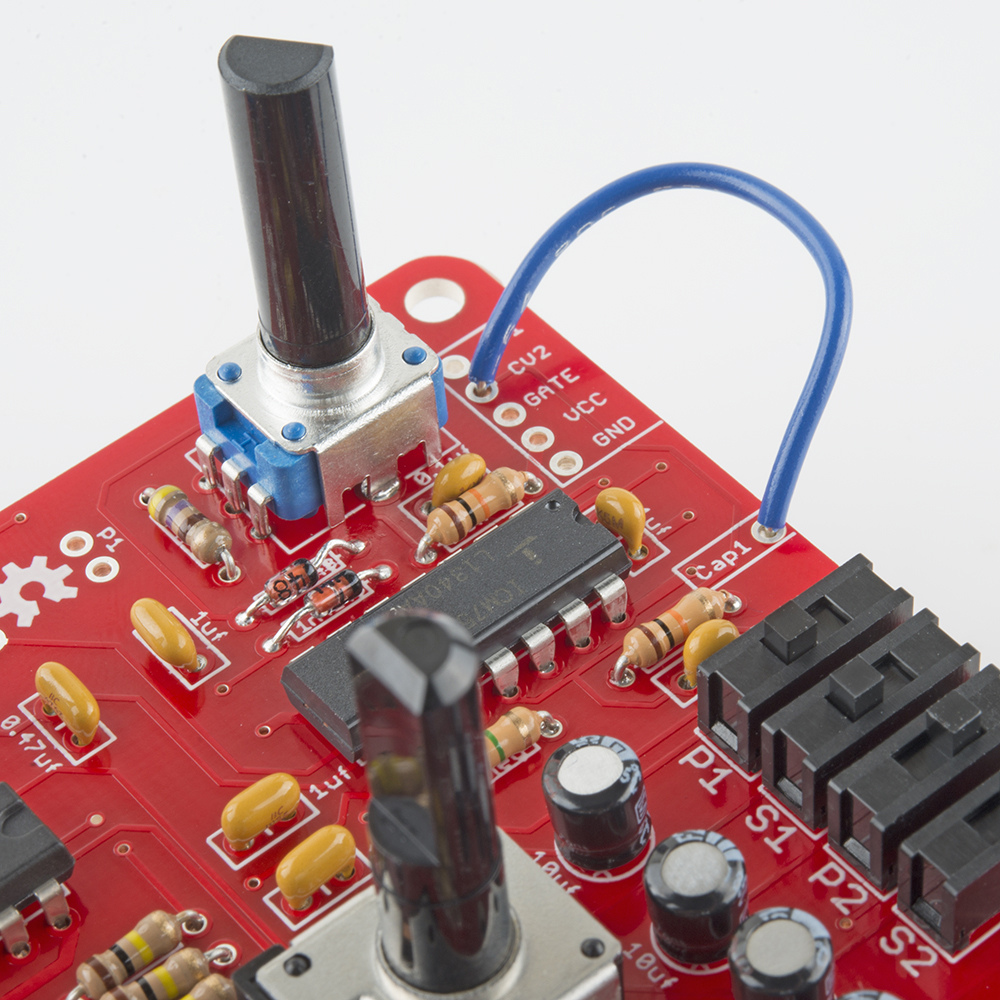
This is a simple form of frequency modulation - it modulates the frequency of the second oscillator using a voltage from the first. The results are a simple form of heterodyning, commonly called "ring modulation" in music effects terminology.
Swapping Components
There are several places where changing a component or two has a large influence over the resulting sound.
Oscillators
The frequency range of each oscillator is set by a capacitor. C3 sets the range for the first oscillator, C4 for the second, respectively 1uf and 0.47uf. They are located between the pitch pots. You can change the range of the oscillators by substituting different caps. Larger caps will take longer to change, thereby lowering the frequency.
If you simply want to be able to tune lower, solder a second cap of the same value (1uf for C3, 0.47 for C4) in parallel with the originals. This will drop everything an octave.
Filter
By changing the capacitors, the filter can be altered a couple of different ways.
The capacitors were originally selected ratiometrically. The parallel combination of C12 and C13 is 2uF, 20 times the 0.1uf of C11. The ratio here determines the width and amount of boost at the center of the peak. Changing the ratio of the caps will alter the value - one simple way to experiment with this is to remove C12, lowering the boost to about 15 dB, from the stock value of 20 dB.
If you keep the ratio the same, but change the values, you can change the center frequency.
You can evaluate and compare the differences by running the filter Spice simulations from the SparkPunk GitHub simulation folder. A decent analysis of bridged-T component parametrics can be found here.
External Interface Header - Room To Grow
You've probably noticed the 5-pin header near the upper-left corner. It's an analog expansion port allowing access to signals that control the 7556.
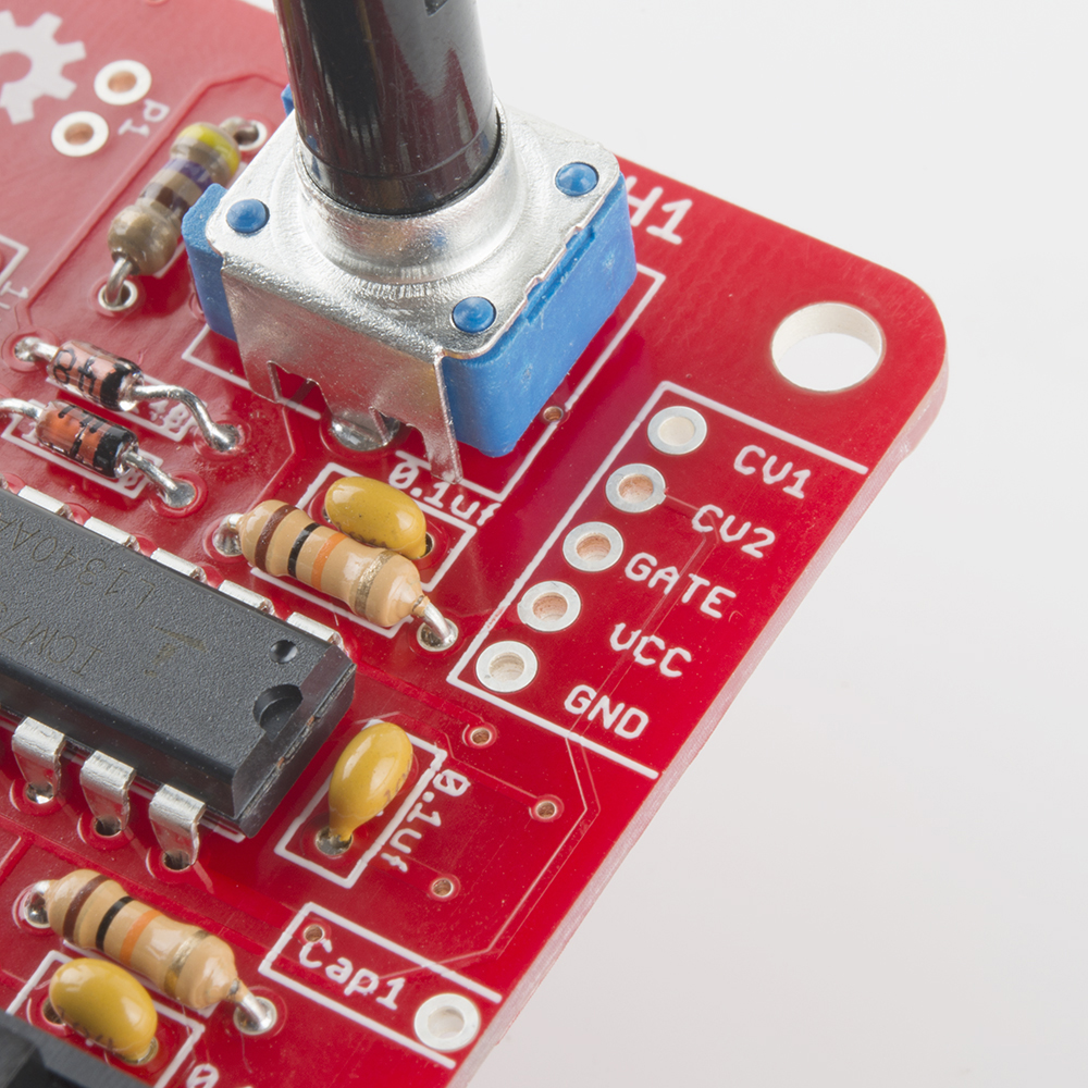
Each oscillator has a control voltage input, marked CV1 and CV2. By feeding a voltage into these pads you can adjust the oscillator frequency. If you're familiar with regular synthesizer control voltage inputs, these aren't what you're expecting. The range is somewhat small and inverted - a higher voltage will lead to a lower frequency. The useful range is roughly from 1/3 VCC to 2/3 VCC, or 3V to 6V. That range gives about an octave of frequency shift. Driving outside that range can cause the oscillator to glitch or stall - worth experimenting with if you like quirky sounds.
The GATE input starts the oscillators. Applying a positive voltage there allows the oscillators to run, just as pressing the trigger button does.
VCC and GND are the power rails of the SparkPunk, so you can power add-on circuitry from the 9V battery.
Experiment On Your Own
We've only scratched the surface here - there are many possible modifications for the SparkPunk!
The sky is the limit!