SparkPunk Sequencer Hookup Guide
 Byron J.
Assembly V - Electromechanical
Controls
Tactile Switch
The first control is the tactile switch, which is located in the lower left corner of the PCB.
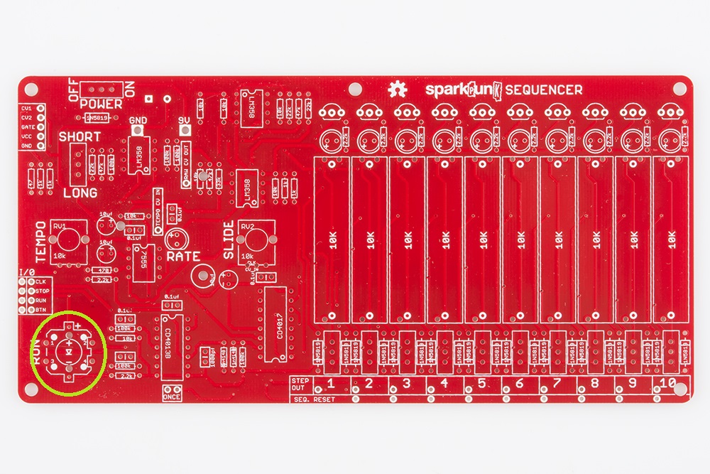
Unlike regular tact switches, this one has an LED in it, so that it can light up when the sequencer is playing. Therefore, the switch is polarized. There is a small "+" sign embossed in one of the white plastic tabs. This matches up with the "+" on the board, as seen in the photo below.

The tact switch legs are already formed so that it will lock in place while you solder, but it can take extra effort to get those legs into the PCB holes. Apply gentle pressure until they snap through, and the body of the switch sits squarely on the PCB. Then solder it in place.
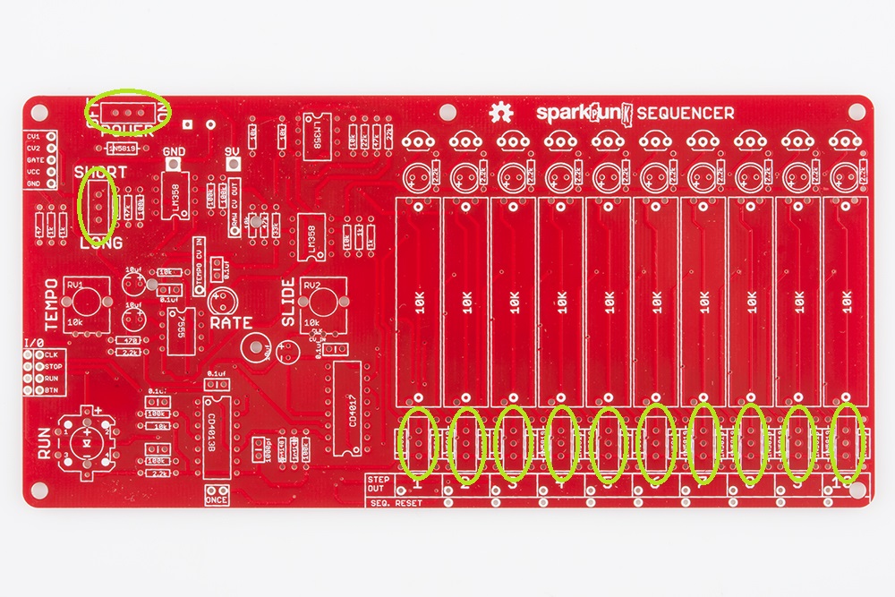
Slide switches
There are twelve small single-pole, double-throw (SPDT) slide switches on the SparkPunk Sequencer. The first two are near the top left corner, and the other ten are arrayed across the lower right edge of the board.
Slide Pots
The ten slide potentiometers are the largest components on the board. They are located in a row across the right side of the PCB.
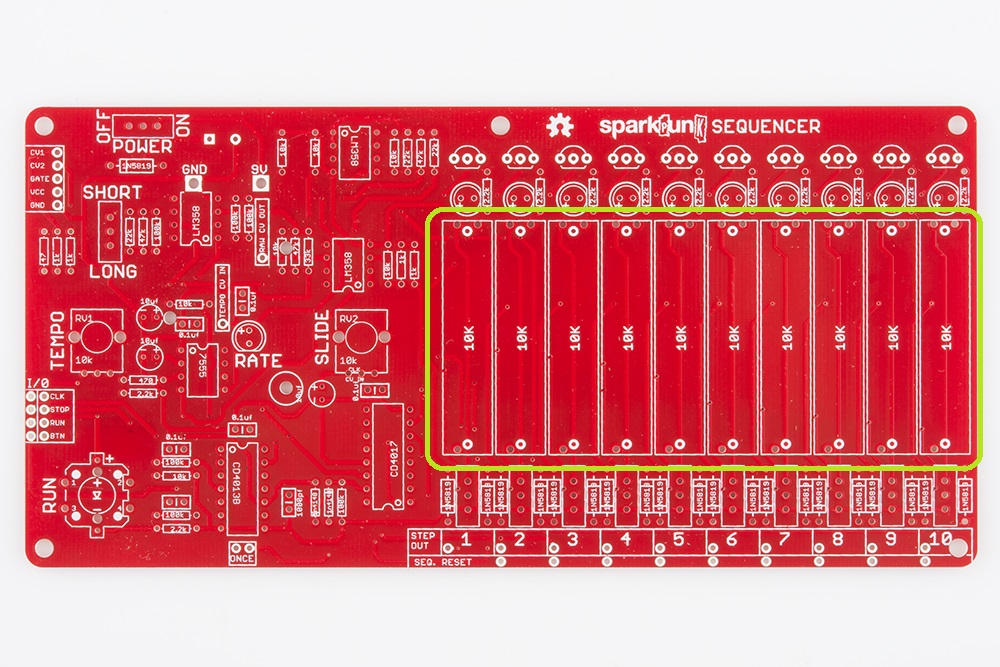
If you take a close look, they only fit in the board one way - one end has a single contact, while the other end has two, which matches the hole pattern on the PCB.
Because they are so large, they can be difficult to keep aligned while soldering. A piece of removable tape can help hold them in place while you work. We had blue painter's tape handy, so we used that.
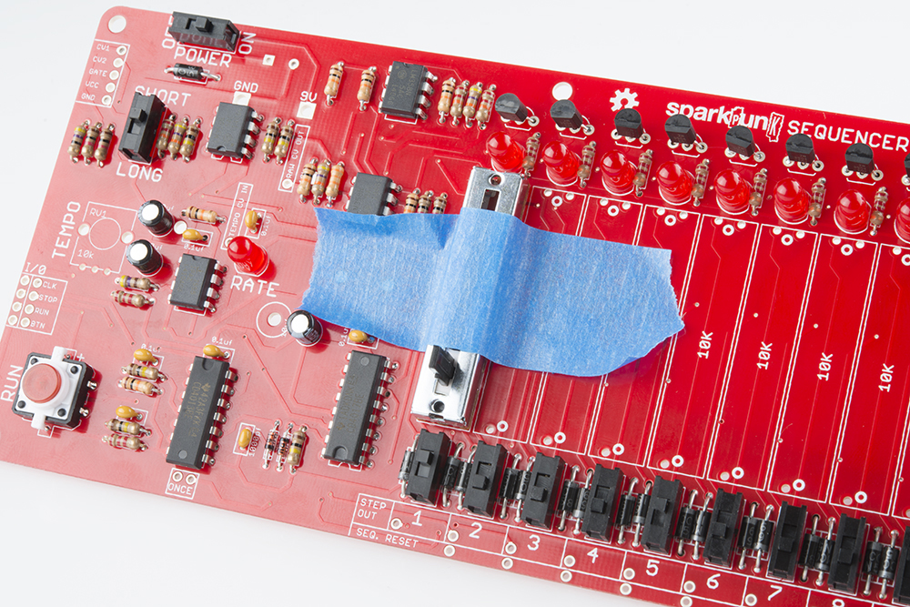
Tape a single slider in place, then solder it down. You can work your way across the board, taping each slider down and soldering it in turn.
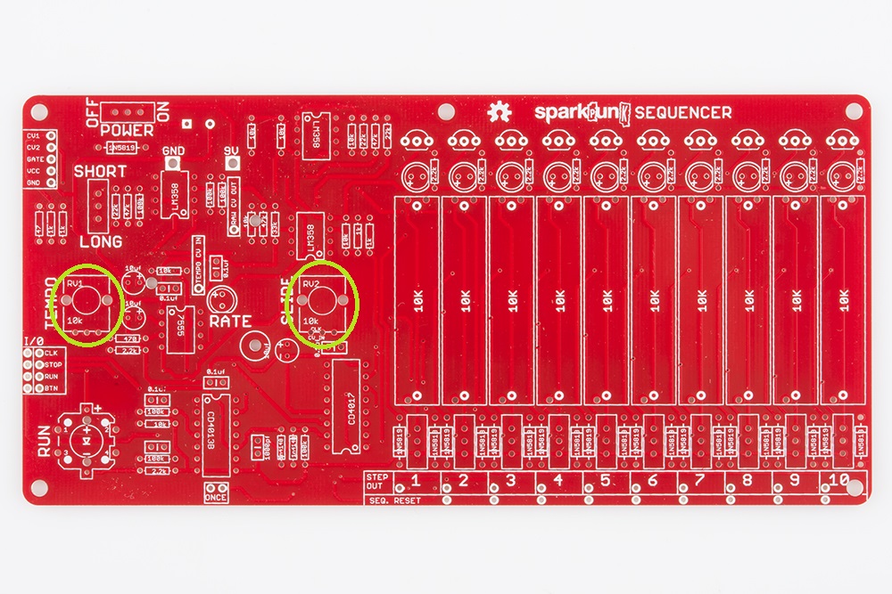
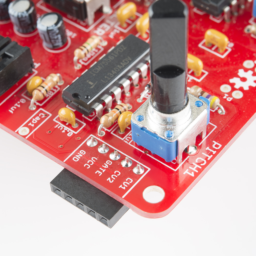
Pots
The rotary potentiometers are the tallest component, so they mark the end of the components on the top of the board.
They're not polarized, but they’ll only fit on the board one way.
It takes some care to get them into the board. If the leads or tabs have been bent in transit, they will need to be straightened out to fit the PCB. To insert the pot, start by lining up the smaller electrical legs, then push the two large tabs into the holes. The tabs are a tight fit - gently rocking the pot from side to side can help. When inserted correctly, the posts on the back of the pot will sit flush on the top of the PCB.
When you solder them in, first solder down the large tabs for stability, taking care that the pot stays flat on the board. Then solder the other connections.
There are two rotary pots on the PCB, both 10K linear taper (marked "M-B-10K" on the back). They go as follows:
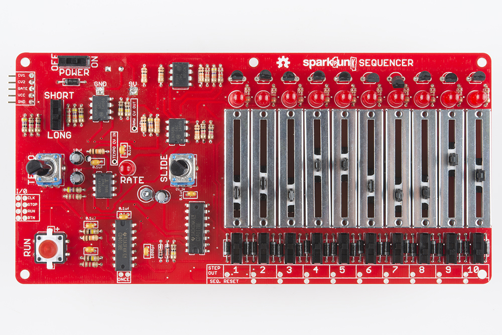
Top Side Completion
We're reaching the home stretch, but before we move on to the power components, let's check that all of the parts we've covered thus far are in the correct place. Take a few minutes to compare your board to the photo below. Check that no components have been omitted, and that all of the polarized components (diodes, ICs, LEDs, and electrolytic capacitors) are facing the proper direction.
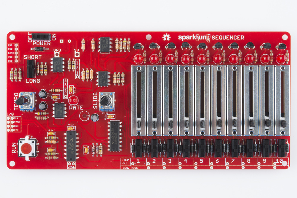
The reason for checking at this point is that we're about to mount components to the back of the board, which will make it harder to rework anything you may have missed.
Power
Battery Box
The battery box is mounted on the back of the PCB. It has two contacts that go through the board.
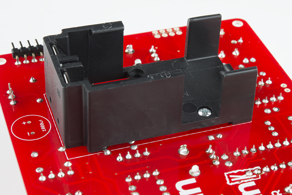
It is secured with a small nut and bolt. The bolt should be inserted from the inside of the battery compartment, and secured with the nut on the front side of the board.
Tighten the bolt, then solder the two leads to the front of the PCB.
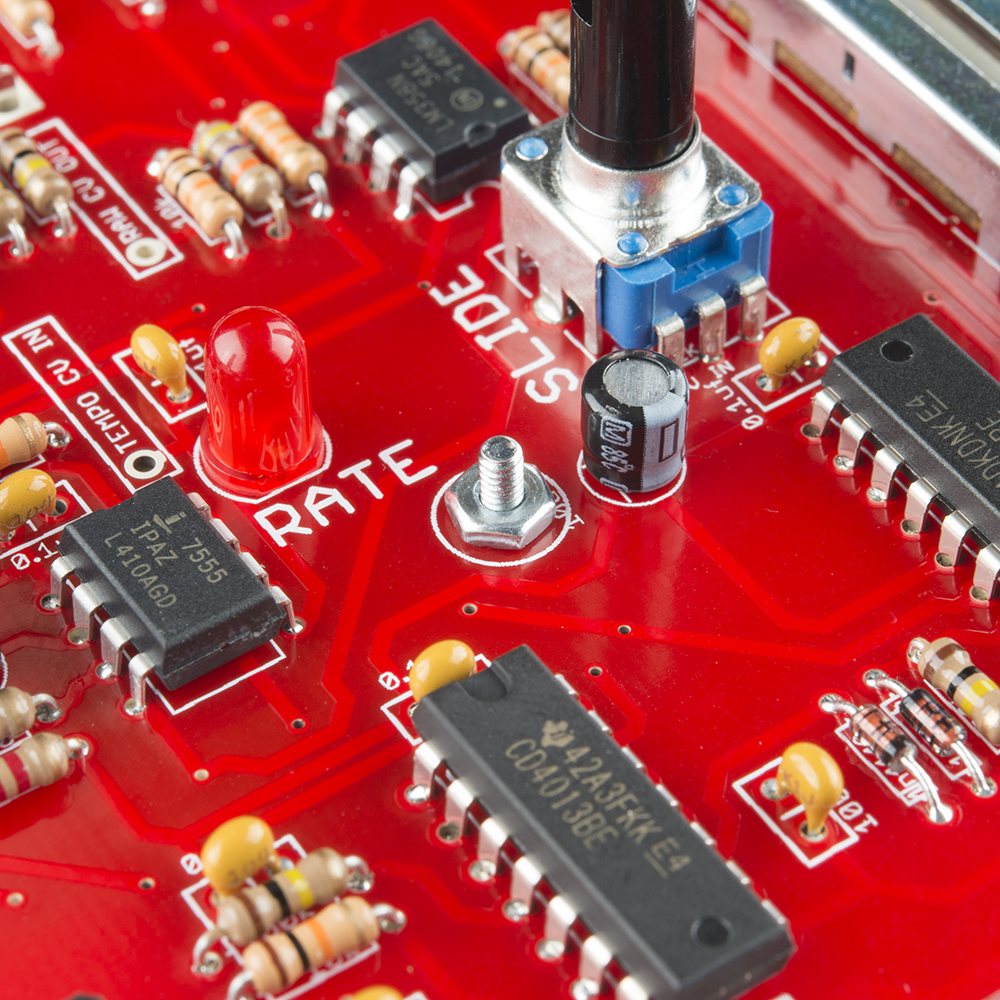
1000μF Capacitor
Now it's time for the capacitor we skipped a couple sections ago. It also goes on the back of the PCB. Like the smaller electrolytics, it is polarized, and needs to be oriented correctly, by matching the lead near the "-" sign on the body up with the PCB pad marked "-", as shown below:

Like the battery box, the 1000 µF cap is soldered to the front of the board.
Connectors
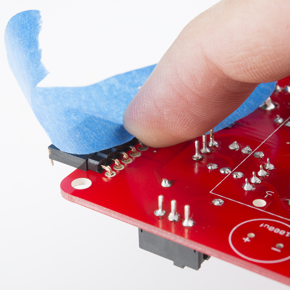
The last set of components are the connectors, a pair of 5-pin right angle headers, one male, and one female. This is the connection that joins the Sequencer to the SparkPunk Sound Generator. It needs to be aligned correctly so that the two can easily plug together.
To get the proper alignment on the connectors, we will use one connector as a jig to hold the other in place. Plug the connectors together, face-to-face. Then place the connector on the back of the sequencer, and tape it in place, as shown below. As you can see, the male side of the connector is on the Sequencer, leaving the female side for the Sound Generator.
Solder the connector to the top of the PCB.
Then remove the female side of of the connector, and solder it onto the Sound Generator. As with the sequencer, it goes on the back of the PCB, soldered to the front. You can use tape to hold it on place while you solder.
Check Your Work
This marks the end of the soldering portion of this kit. You can verify your progress against the picture below.
The only remaining component should be the 9V Battery.
If everything checks out, we are now ready to move on to testing the sequencer.