Stepoko: Powered by grbl Hookup Guide
 MTaylor
Introduction
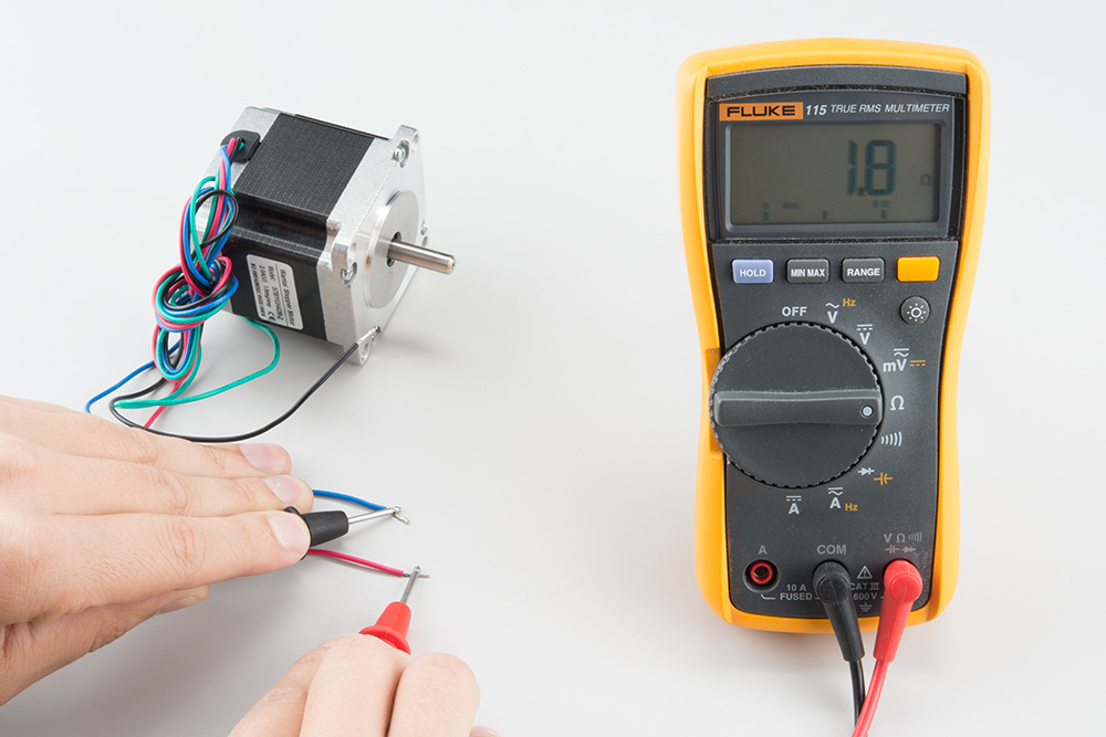
The SparkFun Stepoko is an ATmega328p, Arduino compatible, 3-axis control solution. It's open source, uses open source firmware and works with an open source Java based cross platform G-Code sending application.
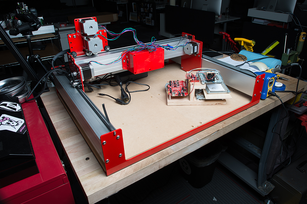
The simplest installation of it consists of just plugging the stepper motors in, but of course hard work pays off. Handy machine control buttons and locating features can be added at taste to give a mill whichever options are desired.
Features:
- 3 stepper connections
- Full, to 1/8 stepping
- Comes with heatsinks installed!
- Options for input and feedback include E-Stop (emergency stop, or general motor drive switch), Reset, Feed Hold, Cycle Start, Homing Location and Probing.
- Has option for spindle direction and PWM control.
- Can be powered from 12-30V.
- Independent axis current limiting adjustments
Required Materials
- Flat-head Screwdriver
- Power supply
- Stepper motors
- USB type-B cable
- Software:
- Univeral Gcode Sender
- A gcode file Github /Examples folder
Suggested Reading
If you still need to assemble your Shapeoko Mill, please consult our Shapekoko Assembly Guide.
- Motor tutorial -- This tutorial covers all types of motors. If you're unfamiliar with stepper motors and how they work, check it out.
Hardware: Overview
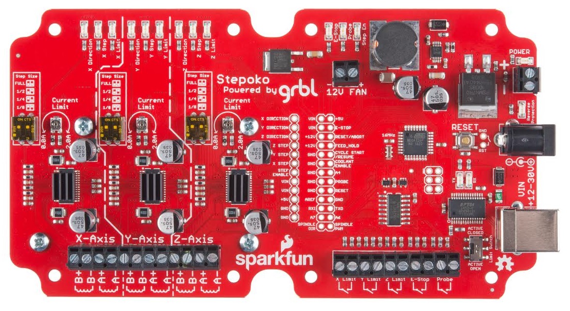
The Stepoko is a complicated board. First, let's take a look at the whole thing, then the various parts will be broken out by function and discussed.
Parts of the top side:
- LEDs
- X, Y, Z Direction -- Denotes polarity of movement
- X, Y, Z Step -- Flashes each time the associated channel steps
- X, Y, Z Limit -- Illuminates when a stop switch is active
- E-Stop -- Illuminates when the stop button is active (shows axis lock has been removed)
- Probe -- Illuminates when probe switch is active
- Step En -- Illuminates to show the controller is ready to step its axes
- Power -- Illuminates when the bulk rail is energized. Shows when back emf is also charging the unpowered rail.
- TX, RX -- Shows communication over the USB.
- Reverse protection -- Illuminates when power has been connected backwards -- Remove power
- Axis connectors
- Switch connectors
- Switch active polarity switch
- Power connectors
- Uno-type 328p
- Reset switch
- USB connection
- Pin Breakout
- Axis drivers -- DRV8811
- Step switches
- Heatsinks
- Power regulation
- Fan connection
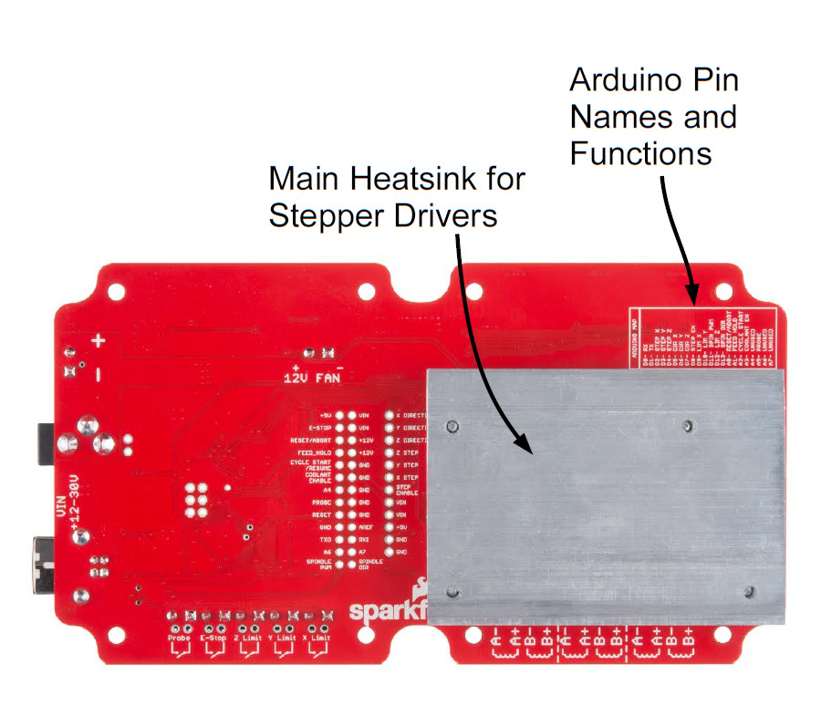
Parts of the bottom side:
- Arduino pin map
- Arduino pin breakout
- Heatsink
Hardware: The System and Power Supply
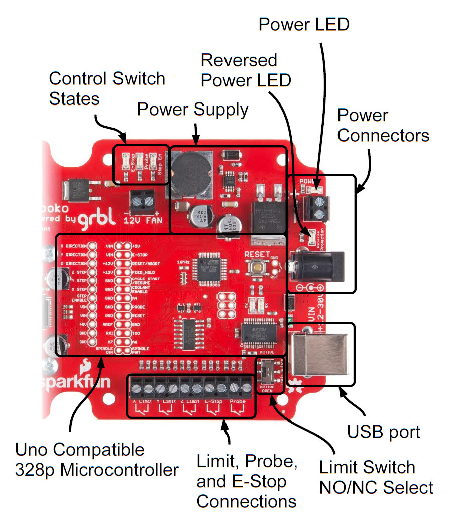
Powering the Stepoko
Stepper motors take a lot more current than most hobby circuits. The Stepoko can supply up to 2.0A each per coil! To get that kind of power, an ordinary wall adapter won't suffice. Apply 12-30 VDC to either the barrel jack or screw terminals, but not both. Use either a power brick or a Benchtop Supply of some kind. Make sure the supply can generate about 3 times the single-coil current for a 3-axis setup. Because of the switching nature of the stepper motors, the maximum current for a single winding is greater than the total current required to run that motor.
Use the following formula:
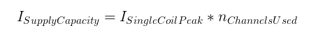
For instance, if two channels are used and set to 1A each, a 2A supply is required.
After power is attached, the blue power LED should light illuminate. If it doesn't, or if the reverse protection LED lights up, remove power and check voltage/polarity of the supply.
The Embedded ATmega328p Microcontroller
The Stepoko is actually an Uno compatible ATmega328p! It's just an Arduino with a grbl shield attached. This is evident by looking near the USB port where the familiar FTDI, Atmel IC, reset button, and even the SPI 2x3 header can be found. In this area, we've even broken out all of the pins that are associated with the microcontroller and power supplies. If you peek at the back of the board, there's a chart in silkscreen that matches the grbl pin functions to the Arduino pin naming convention. It's open source! You can do what you want to it.
To use the microcontroller, attach a USB cable and let your computer enumerate the device as it would with an Arduino. After that, you could program it with the Arduino IDE. It comes with grbl 0.9 though, so don't program it unless you absolutely have to. Even if you revert back to grbl, the grbl settings will be lost and you'll have to program them all in again.
Connecting the control switches
The Stepoko supports
| Pin Name |
Function |
Location | Wiring |
|---|---|---|---|
| E-Stop |
Disengages the motor drivers |
Breakout pins Screw terminals |
Closed on 'Run' while connected to terminals. Drive high for 'Stop' on pin headers - remove U6 for use |
| Reset/Abort | Breakout pins |
Internally pulled high. Close to ground for function. |
|
| Feed Hold |
Pauses the current job |
Breakout pins |
Internally pulled high. Close to ground for function. |
| Cycle Start /Resume |
Restarts the paused job |
Breakout pins |
Internally pulled high. Close to ground for function. |
| Probe | Detect material |
Breakout pins Screw terminals |
Normally open, connected to terminals. Drive high for active on pin headers - remove U6 for use |
| Reset | Resets the microcontroller |
Breakout pins and 1x2 header by reset switch | Pulled up by design. Close to ground to reset microcontroller. |
| X,Y, and Z Limit |
Stops all motion |
Screw terminals |
Normally open or closed set by switch and wired across terminal pair. |
 |
 |
Hardware: The Stepper Drivers
The stepper drivers consist of three identical circuits, one for each axis. Here, one is shown but the application applies to any of them.

Parts of a single axis circuitry:
- State LEDs
- Direction -- Denotes polarity of movement
- Step -- Flashes each time the associated channel steps
- Limit -- Illuminates when a stop switch is active
- Stepper Motor Connection
- Axis driver -- DRV8811
- Microstepping Control Switches
- Heatsinks -- One each on the driver IC and a collective aluminum slug on the backside
- Current control potentiometer
Operation
At the heart of each axis driver is a DRV8811 IC by Texas Instruments. The microcontroller talks to the 8811 by digital control signals (not serial) that: set the direction, enable the motor, and cause a step. Internally, it has a state machine that matches the coil states necessary to get a stepper motor to perform. Modifying the microstepping switches changes that state machine such that the pattern is correct for the microstepping indicated.
The digital portion of the IC operates from 5V by way of the Stepoko's on-board regulator. This is not enough to drive the motors though. The IC has a separate VIN supply that connects directly to the power jack / screw terminals. Whatever the voltage (12V - 30V) supplied, that voltage will be the driving voltage on the motor coils.
All this work is graciously provided by the grbl software that comes pre-installed, so unless you are building new software, how the 8811 works is really not too important. If you are, the DRV8811 datasheet explains in great detail.
Hardware: Connecting the Motors
The Stepoko is designed to be able to control a multitude of 2-phase stepper motors. These all have two sets of coils that are driven in a particular combination in order to make the motor turn in the correct direction. If this is all new to you, read our tutorial on Motors and Selecting the Right One, in particular the section Stepper Motors. This tutorial has some descriptions of motors with three sets of coils rather than two, but the theory is the same.
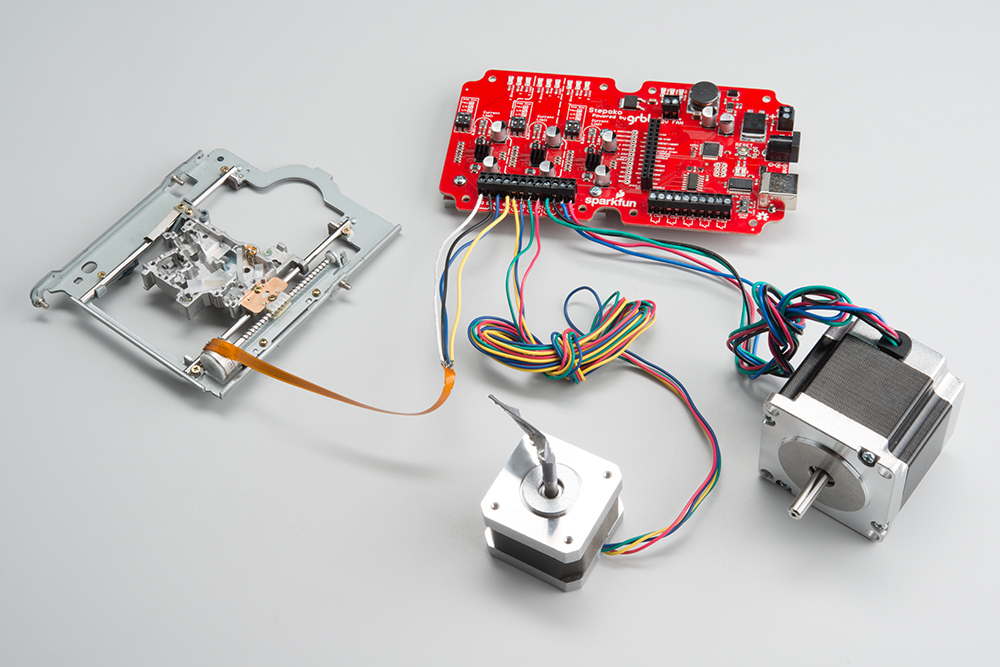
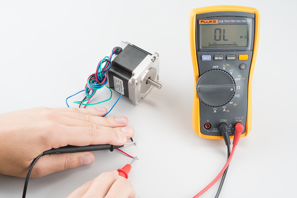
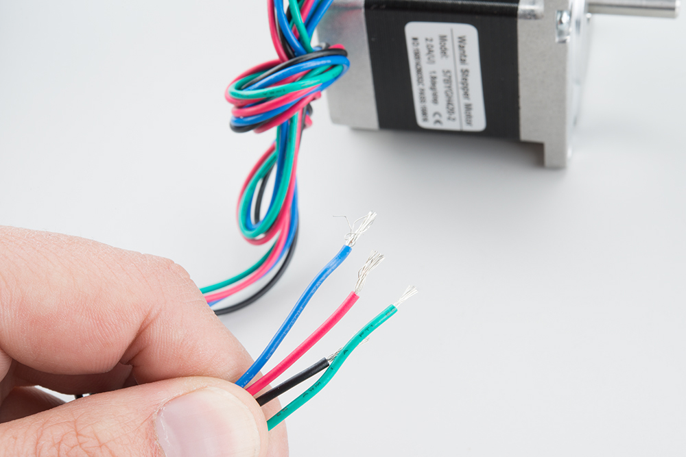
Identifying the Coils
A lot of the time steppers come from a 'motor box' on a hobbyist's shelf, and may not have ratings or part numbers. If there are four wires, chances are it's a stepper. The coils need to be identified though, so take out a multimeter and look for continuity between wires. If the motor has four wires, with two pairs that have a similar resistance, you've found the coils!
 |
 |
Alternately, with the datasheet the wires should be indicated. An example datasheet from our general purpose motor shows a simple wiring diagram with the two coils.
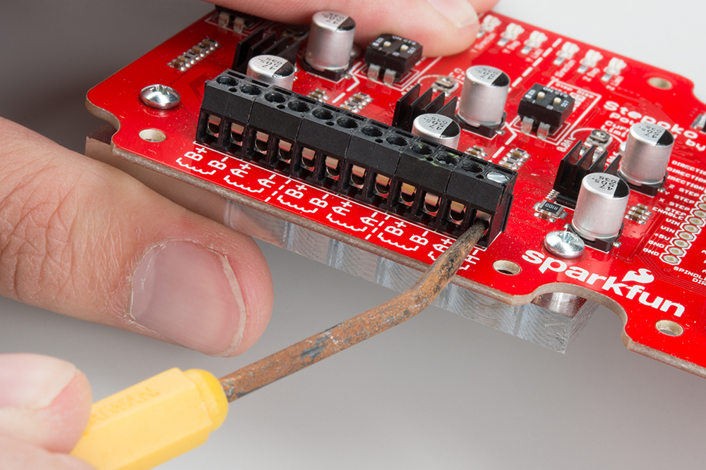
Attach the motors
The two coils of the motor correspond with the 'A' and 'B' terminal pairs on the board. Including the fact that you can put the coils in backwards, there are 8 possible ways to connect two coils! But which one goes where? Don't even worry about it. If one is backwards, or if coils 'A' and 'B' are swapped, the motor will just spin in the other direction, which can be set in software.
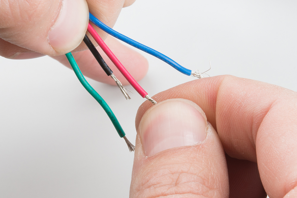
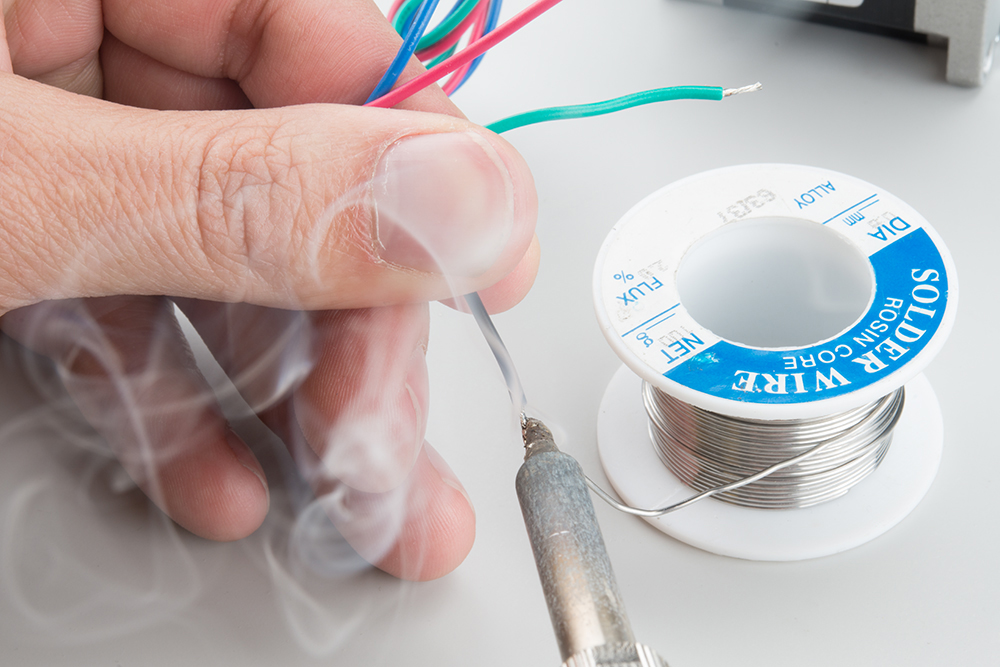
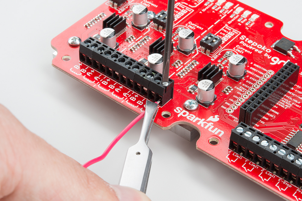
More worrisome is how to convince the stranded wires get into the terminal blocks and then, stay there after they have been tightened. Tinning the leads can make the whole thing go smoothly.
 |
 |
 |
Sometimes the terminal springs are tight from the factory. To help ease connection, back out the termina screw until it's flush with the terminal block, gently open the contact, and use a tool to push from the tinned end.
 |
 |
 |
Hardware: Setting the Current
Before powering up the Stepoko, set the desired current for each attached motor. The current control potentiometer scales the peak drive current from 0 to 2 amperes. There a few methods of setting the current.
Set by 'Dead Reckoning'
This is the preferred method.
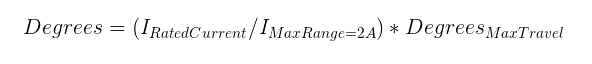
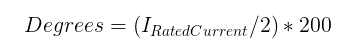
The trimpot can swing through 200 degrees of motion, and covers a range of 2 amps. Turn the trimpot counter-clockwise gently until it hits the stop, then clockwise a number of degrees for the desired current. The example datasheet from the previous section lists the motor as being 0.33 A capable. Set the knob to 33 degrees from counter-clockwise stop.
Use this formula for other motors:
Set by Test
If you have more experience, you may opt to set the current by feel.
Start by setting all the trimpots to slightly off their counter-clockwise stop. Then, fire up the Universal Gcode Sender software (described later) and connect to the Stepoko. This enables all the motor drivers and will lock their position. Now, attempt to move the motor. If the motor moves easily, carefully turn up the channels and repeat the test until the force required to move the motor (slipping poles) is greater than the expected lateral force exerted by the tool head.
Set by Current-Shunt Measurement
The most scientific method to know a thing is to measure it. To do that, you'll need a scope and a steady hand.
There are 6 current sense resistors on the Stepoko that can be identified in the schematic, and by finding the larger resistors near the drivers. Each has one end grounded while the other is connected to the active driving circuitry. By adding a probe ground to one end and stabbing the other end, both positive and negative coil current can be measured.
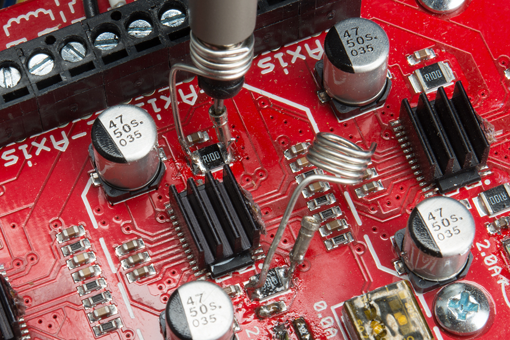
The resistor itself is 0.1 ohms in resistance. At the max current setting of 2A, and by following ohm's law, the max voltage read across this resistor is 0.2V, or 200 millivolts. This is quite low. A scope with 8 divisons on the screen has to be set to 50mV per divison so that positive and negative 2A can be read. At this vertical scale, the electromagnetic radiation from the giant current loads of the motor will be picked up by the extra few inches of the probe, which is why a the shortest possible loop of wire at the probe end is desired.

Adjust the plateau average to the rating of the motor.
Hardware: Dealing with Heat
To get the heat out of the driver ICs, the Stepoko comes equipped with three heatsinks on the top and a large aluminum mass on the backside. When setting up the Stepoko, be careful to check the temperature often to make sure it is not too hot to touch. Generally speaking, the harder the motors are driven, the more heat will accumulate on the heatsinks.
Here are a few methods of dealing with the heatsinks.
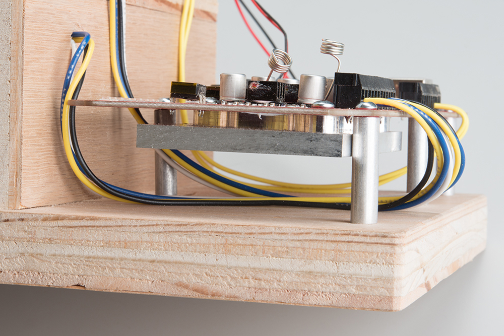
Provide air space
For small motors or mills that don't have a large cool mass of metal to wick out the heat, make sure the Stepoko is lofted and that air can passively circulate around the heatsinks.
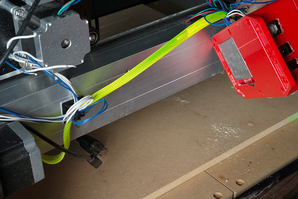
Attach a path for cooling
The intent of the aluminum slug on the backside is to conduct heat to the mill itself for cooling. The height is perfect to pass through a hole cut in the SparkFun Big Red Box enclosure so that the whole thing can be mounted to a thermally conducive surface.
Add a fan
There is a connection on the Stepoko for attaching a single, or multiple 12V fans. This connection is regulated to 12V and unswitched, so fans connected there will run whenever the Stepoko is powered from 12-30V.
Software and Firmware Overview
Milling is a little more interactive than just sending a job to a printer. After the hours put into modeling, the model files are converted into what's called G-code by CAM software. Then, the G-code is sent to the mill by some machine control software (in our case, universal G-code sender). The mill itself runs firmware which can interpret what the machine control software is saying and in turn, drives the stepper motors to move the mill. Whew.

The solid modeling, design work, and CAM software are not in the scope of this hookup guide, and from here on it is assumed that you have some gcode from somewhere. Several examples exist in the Stepoko github including a 1x1 inch square, a few 10x10 inch squares, and the SparkFun flame.
Software: Machine control (Universal G-code Sender)
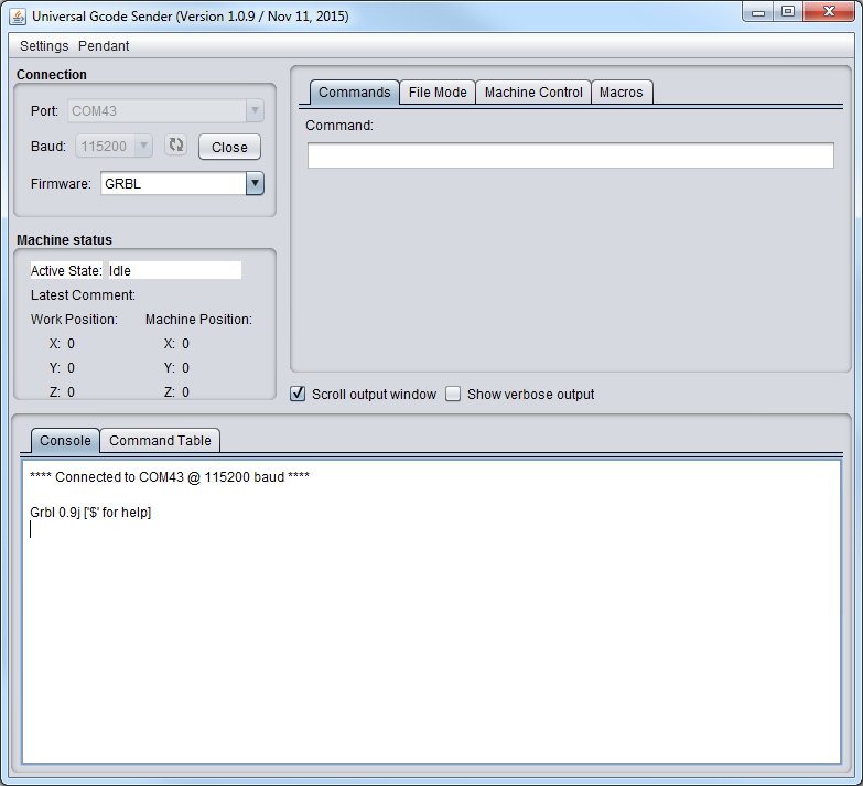
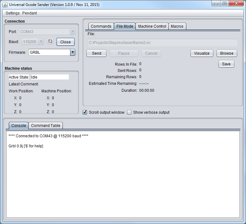
Once G-Code files have been created, a program is needed to parse them and issue the commands to the Stepoko. A good open source one that works well with the Stepoko (and all grbl hardware) is Universal G-Code Sender.
As of writing this, 1.0.9 is the latest stable build. Most people will want this as a zip archive rather than having the github source. Download it, unzip it into a directory, and run the batch file for windows, or shell script for mac/linux.
Make sure you are connected to the Stepoko. Once the program is loaded, you can set the connection parameters, and click 'Open' to get a connection to the mill. Use 115200 baud and the port that appears when you attach the Stepoko. If all goes well, the grbl firmware will reply with its version number.
Firmware: grbl for the Stepoko
The Stepoko is shipped with the latest grbl, (v0.9) as of this writing. The grbl project is highly developed and can be found in github, complete with a wiki that describes in detail what the settings do.
Direct links to the project and wiki:
- grbl Github Repository -- Github Project
- grbl github's wiki -- Project wiki
From the grbl github repository:
- Non-Modal Commands: G4, G10L2, G10L20, G28, G30, G28.1, G30.1, G53, G92, G92.1
- Motion Modes: G0, G1, G2, G3, G38.2, G38.3, G38.4, G38.5, G80
- Feed Rate Modes: G93, G94
- Unit Modes: G20, G21
- Distance Modes: G90, G91
- Arc IJK Distance Modes: G91.1
- Plane Select Modes: G17, G18, G19
- Tool Length Offset Modes: G43.1, G49
- Cutter Compensation Modes: G40
- Coordinate System Modes: G54, G55, G56, G57, G58, G59
- Control Modes: G61
- Program Flow: M0, M1, M2, M30*
- Coolant Control: M7*, M8, M9
- Spindle Control: M3, M4, M5
- Valid Non-Command Words: F, I, J, K, L, N, P, R, S, T, X, Y, Z
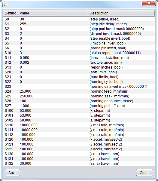
In our factory, after programming the firmware onto the Stepoko, we put the following settings directly into the ROM of the ATmega328p. These are held even when power is removed, or until they are changed by the user through the serial (or Universal Gcode Sender) interface.
These default settings are appropriate for the Shapoko 3 mill.
$1=255 (step idle delay, msec)
$2=0 (step port invert mask:00000000)
$3=5 (dir port invert mask:00000101)
$4=0 (step enable invert, bool)
$5=0 (limit pins invert, bool)
$6=0 (probe pin invert, bool)
$10=255 (status report mask:11111111)
$11=0.020 (junction deviation, mm)
$12=0.010 (arc tolerance, mm)
$13=0 (report inches, bool)
$20=0 (soft limits, bool)
$21=0 (hard limits, bool)
$22=0 (homing cycle, bool)
$23=0 (homing dir invert mask:00000000)
$24=100.000 (homing feed, mm/min)
$25=1000.000 (homing seek, mm/min)
$26=25 (homing debounce, msec)
$27=5.000 (homing pull-off, mm)
$100=40.000 (x, step/mm)
$101=40.000 (y, step/mm)
$102=40.000 (z, step/mm)
$110=5000.000 (x max rate, mm/min)
$111=5000.000 (y max rate, mm/min)
$112=5000.000 (z max rate, mm/min)
$120=400.000 (x accel, mm/sec^2)
$121=400.000 (y accel, mm/sec^2)
$122=400.000 (z accel, mm/sec^2)
$130=425.000 (x max travel, mm)
$131=465.000 (y max travel, mm)
$132=80.000 (z max travel, mm)
Firmware: Configuring grbl and Calibrating
This section covers calibration of the axes. The settings take a parameter of steps required for each millimeter of motion, but factors such as microstepping and mill geometry come into play.
Calibrating
When working with a new motor, a few steps need to be taken to get it moving correctly
- Get the number of steps per revolution
- Decide on microstepping value
- Determine ratio of motor revolutions to carriage motion
- Calculate steps per mm
- Drive the carriage a known distance
- Measure error and apply to settings
The Initial steps/mm Setting
If using a mill with known geometries, you're in luck! Punch in the steps/mm as given.
If using recycled parts or variable materials (like belts), do some basic math to get an approximate first-setting.
Do This for Each Axis:
While turning the motor, measure the distance traveled in mm. Then, calculate steps per mm based on
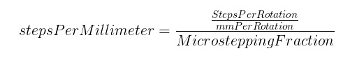
For example, with a 200 steps/rev motor that travels 42mm per revolution and 1/2 microstepping,
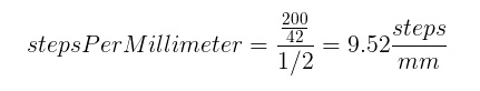
Now, using the 'machine control' tab in Universal Gcode Sender, instruct the mill to move 1 inch (or some number of millimeters). Is it close? Reset the mill, mark the location and repeat. Make a measurement of the true movement.

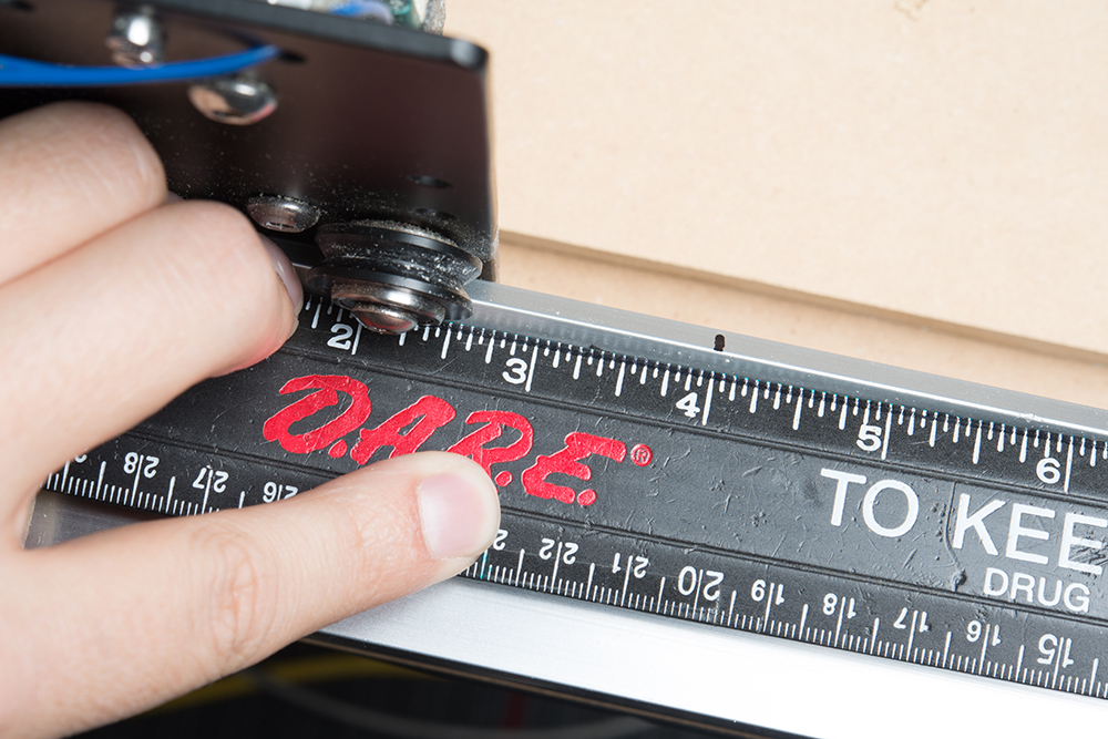
Now, modify the original setting by a ratio of the expected and measured movement. Another way to think of it is, what's the percent error?
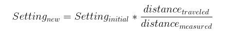
For my example, I intended to drive 1 inch but actually drove 1.3 inches. I take the original setting of 9.52, multiply by 1/1.3 to get 7.32. After programming the new setting, the movement is dead-on (or bang-on if using mm).
Cutting a Square
If you've never used a mill before, start by cutting out a simple shape. For this, the design step will be skipped. We'll go directly to CAM and use it to put in a basic shape.
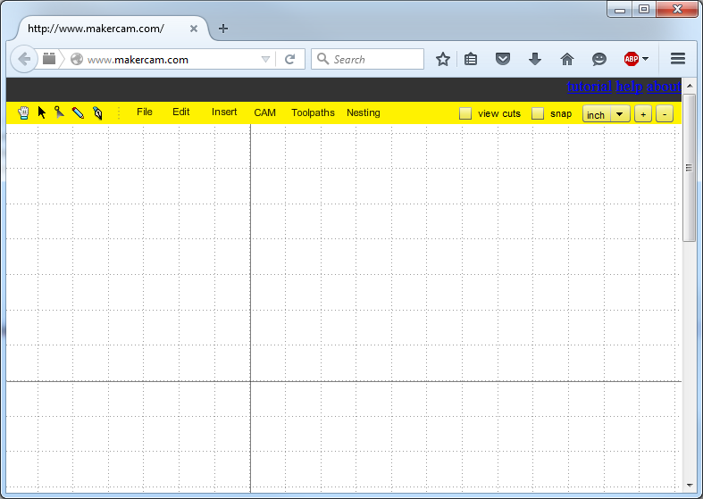
The first step is to open MakerCam in a new window. If you have ad blocking software enabled, you may have to disable it.
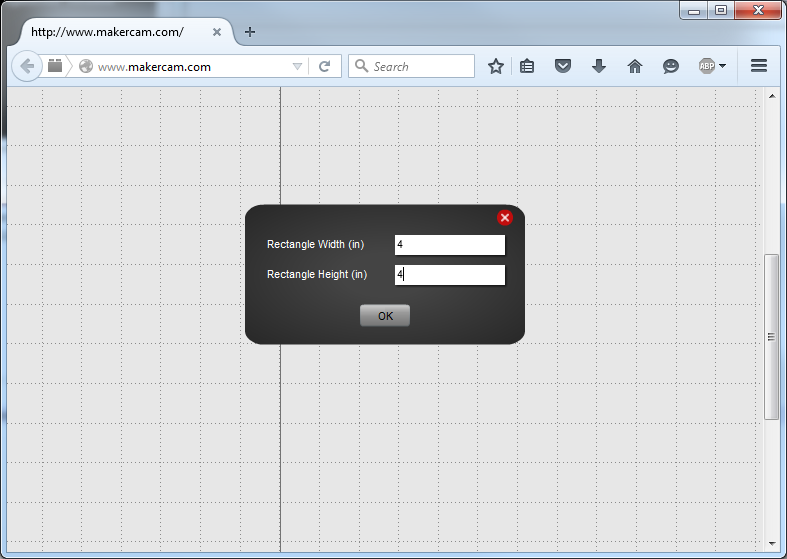
Next, use the menu to add a square (or any shape). A window will open that lets you specify some of the parameters.
The real purpose of the cam software is to determine how to make a real machine do some movement that yields the desired shape remaining at the end of the whole thing. To do this, drop down the CAM menu and select profile. This means the tool will move around the outside of whatever the shape is that's selected. Other options are engrave, to follow the line exactly, and pocket, which removes all the material inside the shape.
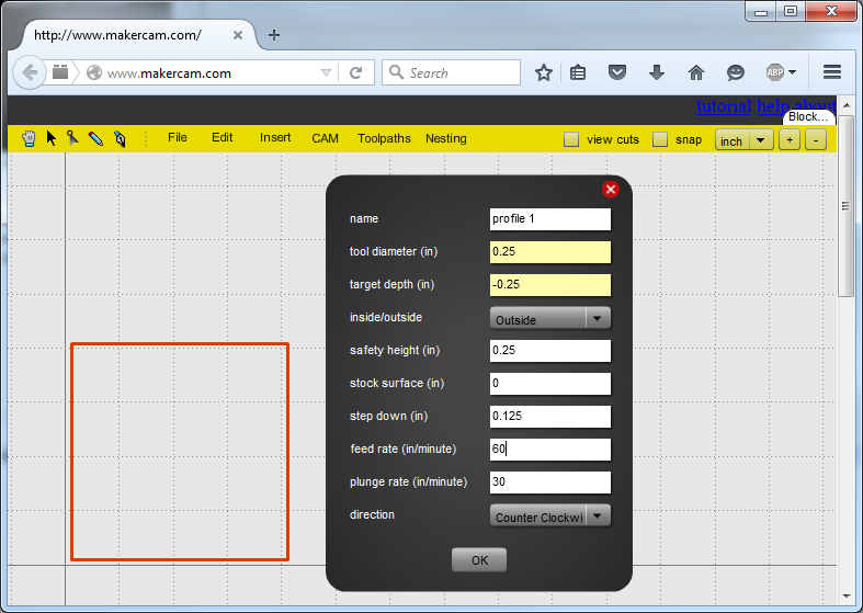
From this window, the cam software takes into account the geometries of the actual mill. Set the tool diameter, safety height (how far above the surface to go before X-Y movement), and step increment. Stock surface is important too, but for now leave it a 0. It can be used for multiple path jobs where one path takes the stock surface down, and the next cuts from that level.
I've selected quarter inch depth with eighth inch depth per cut. Hit 'OK'
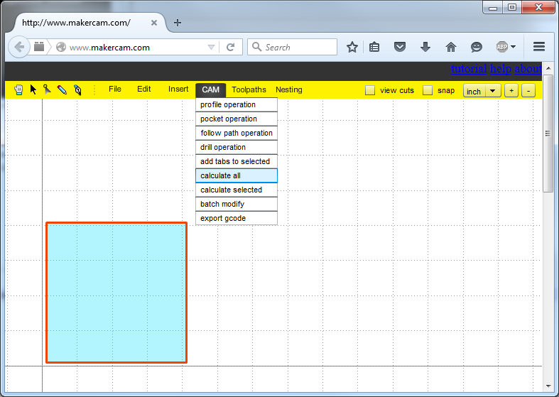
Now we need to calculate a path based on the parameters. From the CAM menu, select 'calculate all'
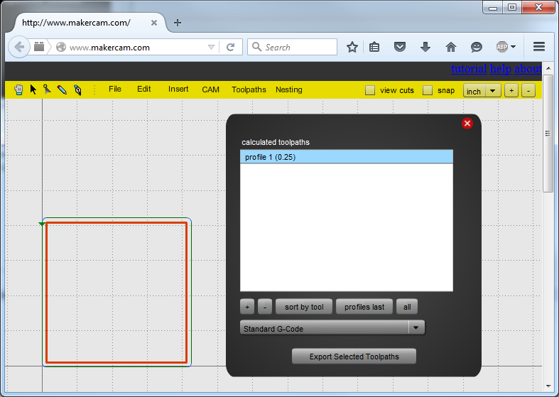
Now a green line with arrows appears above the part. This shows how the tool will move. This path becomes the gcode, so the next step is to export (again, from the CAM menu). There should only be one path available to select.
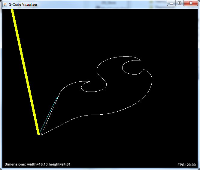
Got it? OK, now put MakerCam aside and open Universal Gcode Sender. Then load the file and click visualize. By holding down the mouse button in the visualization window, the view can be rotated.
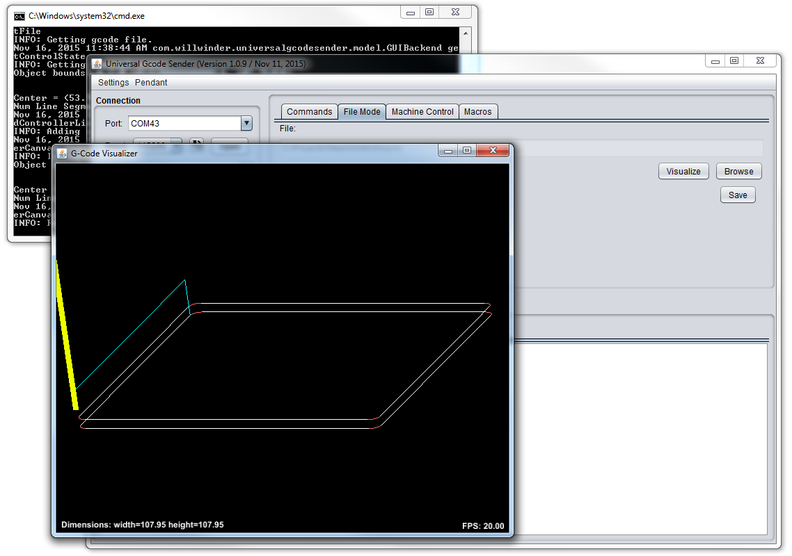
When you're confident that the mill head has enough room to complete the pass, zero it out, and hit go. Running a couple inches above the table is a good way to build confidence in the job. Be ready to hit the estop if something goes amiss. When you're good and ready, turn on your active cutting device and let 'er rip.
Cutting and Engraving a SparkFun Coaster
Squares are alright, and it's fun to watch the machine move around, but eventually you'll want to actually cut some real shape out with the mill. I've put this Shapoko Coaster Project together to show all the steps of cutting a project with a mill.
Shapeoko Coaster Project
November 20, 2015
This uses open source software for all steps:
- Create design in inkscape
- Create took paths through makercam.com
- Send gcode with Universal Gcode Sender
- Stepoko runs grbl on the mill
Watch a video of the coaster being made below:
Resources and Going Further
This is all the basic information about applying the Stepoko to mills. If you would like more information about a particular step, please comment.
Looking into the future
- McMaster-Carr - Order tools online, as well as any part you would ever need.
- CamBam Software - This CAM software is better than the free one and is reasonably priced. It has a 40 day use trial. I would highly recommend trying it out.
Links mentioned in this hookup guide
- DRV8811 -- Texas Instruments product page.
- DRV8811 datasheet -- Direct link to the driver datasheet.
- Universal G-Code Sender -- Github repository.
- grbl Github Repository -- Source code.
- grbl github's wiki -- Information on settings.
- MakerCam -- Web based CAM software.