Stepoko: Powered by grbl Hookup Guide
 MTaylor
Hardware: Setting the Current
Before powering up the Stepoko, set the desired current for each attached motor. The current control potentiometer scales the peak drive current from 0 to 2 amperes. There a few methods of setting the current.
Set by 'Dead Reckoning'
This is the preferred method.
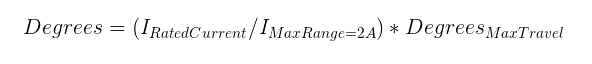
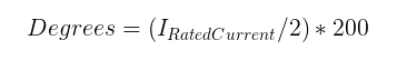
The trimpot can swing through 200 degrees of motion, and covers a range of 2 amps. Turn the trimpot counter-clockwise gently until it hits the stop, then clockwise a number of degrees for the desired current. The example datasheet from the previous section lists the motor as being 0.33 A capable. Set the knob to 33 degrees from counter-clockwise stop.
Use this formula for other motors:
Set by Test
If you have more experience, you may opt to set the current by feel.
Start by setting all the trimpots to slightly off their counter-clockwise stop. Then, fire up the Universal Gcode Sender software (described later) and connect to the Stepoko. This enables all the motor drivers and will lock their position. Now, attempt to move the motor. If the motor moves easily, carefully turn up the channels and repeat the test until the force required to move the motor (slipping poles) is greater than the expected lateral force exerted by the tool head.
Set by Current-Shunt Measurement
The most scientific method to know a thing is to measure it. To do that, you'll need a scope and a steady hand.
There are 6 current sense resistors on the Stepoko that can be identified in the schematic, and by finding the larger resistors near the drivers. Each has one end grounded while the other is connected to the active driving circuitry. By adding a probe ground to one end and stabbing the other end, both positive and negative coil current can be measured.
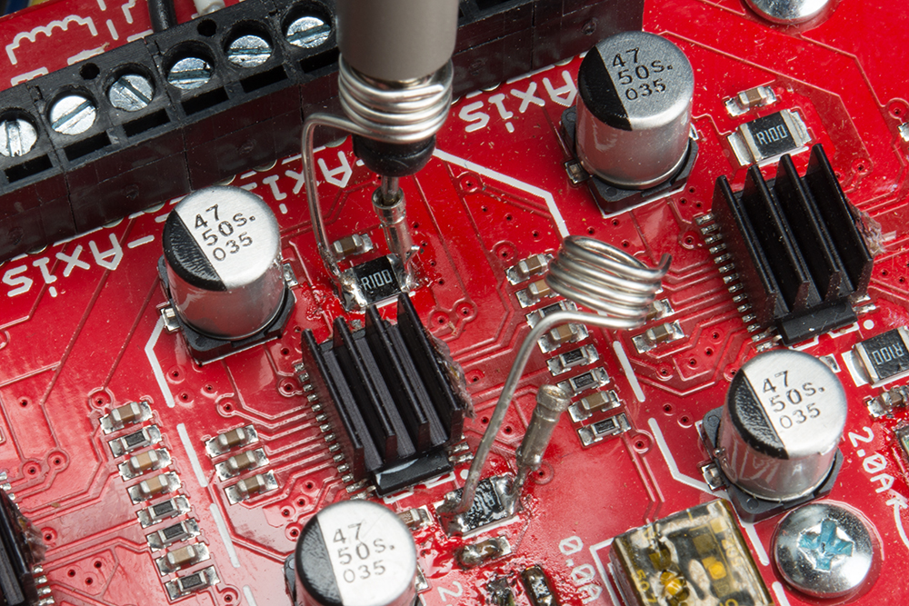
The resistor itself is 0.1 ohms in resistance. At the max current setting of 2A, and by following ohm's law, the max voltage read across this resistor is 0.2V, or 200 millivolts. This is quite low. A scope with 8 divisons on the screen has to be set to 50mV per divison so that positive and negative 2A can be read. At this vertical scale, the electromagnetic radiation from the giant current loads of the motor will be picked up by the extra few inches of the probe, which is why a the shortest possible loop of wire at the probe end is desired.

Adjust the plateau average to the rating of the motor.