Sunny Buddy Solar Charger V13 Hookup Guide
 SFUptownMaker
 Hooking It Up
There are three parts to consider when embedding the Sunny Buddy into a project:
- Solar Panel Input
- Battery Output
- Load
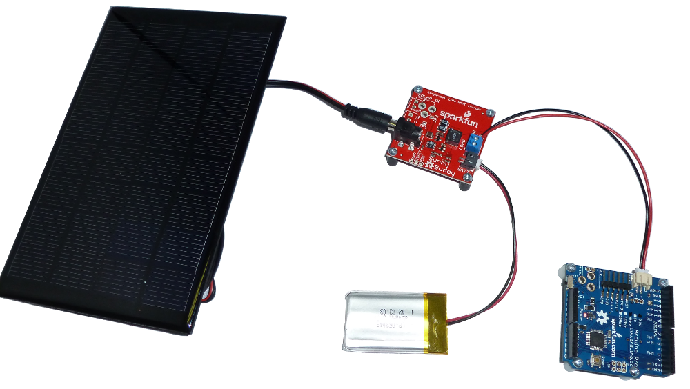
Solar Panel Input
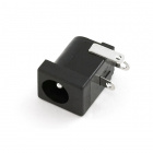
The input side of the Sunny Buddy comes with a common barrel jack installed.
The following solar panels can be plugged directly in to the Sunny Buddy's female barrel jack with ease.

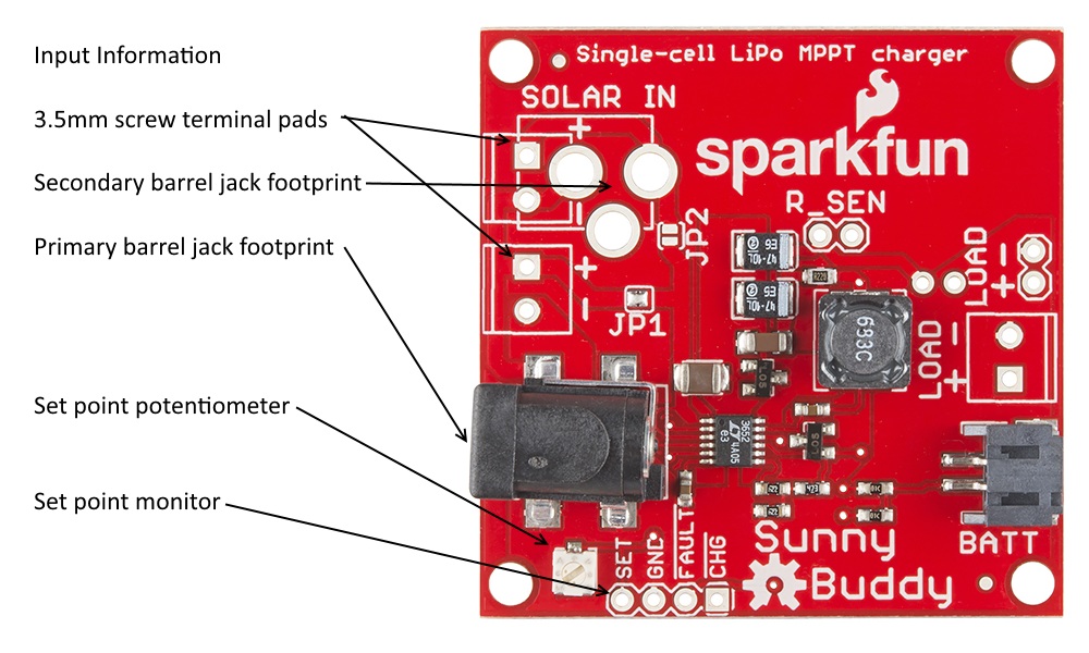
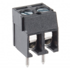
There are also additional footprints for attaching 3.5mm screw terminals or an additional barrel jack to the board.
Please note that if you intend to use two solar panels, you must clear solder jumper JP1 (it ships closed by default) and close solder jumper JP2 (it ships open by default). Failure to do this will result in the second supply being left unconnected. If both jumpers are left unconnected, no power will be sent to the board. If both jumpers are shorted, the second panel will be shorted out and contribute no power to the system but may be damaged by being short circuited.
The maximum recommended input to the board is 20V; this is a stack of two of our panels. The minimum is 6V, but most solar panels should be above this.
A useful trick for monitoring the input current of a single-panel system is to open JP1 and close JP2, then connect an ammeter between the + pads on the two 3.5mm footprints. This will allow you to monitor the current draw from the solar panel. Note that JP1 must be resoldered and JP2 reopened before attempting to use the SunnyBuddy without the meter in place!
Setting the Input Current Limit
The revised Sunny Buddy has an input set point potentiometer. This allows the user to set an input voltage at which the Sunny Buddy will reduce its current draw to maintain peak power input from the solar panel.
You'll want the voltage at this node to be at 2.7V when the solar panel is at the "knee" voltage we discussed in the Why MPPT? section above. Some solar cell manufacturers may give you this information; the manufacturers of our panels, however, have not. You can either take the hard road and characterize your cell (ick) or take the easy road and make an educated guess that the MPPT point will be at about 90% of the voltage you see when you're in full sun.
To find that point, plug your solar panel into the Sunny Buddy, but don't put a battery or load on it. Measure the voltage from the "SET" pad to the "GND" pad next two it, and tweak the potentiometer until that voltage is about 3V. At that point, the Sunny Buddy will draw current until either 450mA is going to the load and the battery or the solar cell voltage is 90% of its full-sun open-circuit nominal voltage.
Battery Output
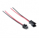
The output of the Sunny Buddy is intended to charge a single Polymer Lithium Ion cell. A 2-pin JST connector is populated, and will mate up to most of the LiPo batteries SparkFun sells.The load should be connected in parallel with the battery; again, footprints for a 3.5mm terminal or a standard .1" spaced header have been provided.
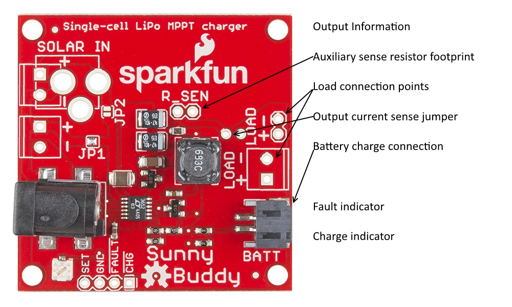
The charge current is set by resistor R1 in the schematic. By default it comes set to a maximum charge current of 450mA. It's recommended that batteries not be charged at greater than their capacity rating; thus, the smallest battery that should be charged with the Sunny Buddy is 450mAh.
The revised Sunny Buddy adds an additional sense resistor footprint in parallel with the built-in resistor. The charge current is equal to .1/(R1||RSen); putting a 1-ohm resistor on the Rsen pads will increase the charge current to ~550mA. R1 can be desoldered from the board if charge currents below 450mA are desired.
Note that it is possible to set the charge current to impossible levels. If the current level is too high, the inductor will saturate, which will limit the output current artificially.
Finally, note that there's a jumper on the board that can be cut to allow you to monitor the output current of the charger. You'll need to reconnect the jumper pads after you've finished taking measurements.
The Load
The load can be connected to either the 0.1" or 3.5mm spaced pads on the right edge of the board.


It's important that the load not be too heavy; since it is in parallel with the battery, it will steal some of the charge current from the battery when it is operating.
To avoid this, consider putting active circuitry to sleep whenever possible, or using a microcontroller to turn parts of the load on or off as they are not needed. Methods for doing this are beyond the scope of this tutorial.