The ClockClock Project
Introduction
What time is it?! It's time for an awesome Alchitry project, that's what! In this tutorial I’m going to walk you through how I built a ClockClock using the Alchitry Au to control all the motors.
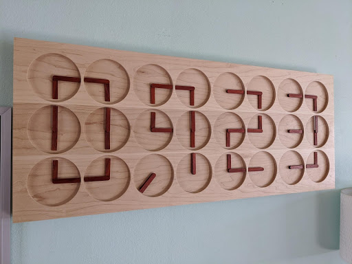
What is a ClockClock? It is simply a clock made of clocks! The idea is to use many analog style clocks together to form the digits of the time. So meta.
First, let me start by saying this wasn’t my original idea. I came across this concept a few years ago and always thought it would be a great demo FPGA project since it requires so many control signals. The original clock can be found here.
There are a couple reasons this project makes such a great FPGA demo project. First, the clock requires 48 stepper motors. There are 24 “clocks” and each one has two independent hands. Using a standard step/direction stepper driver means you need two control signals per motor or 96 outputs. I wanted to be able to disable the drivers when the clock was stationary to save power. This added four more outputs (one for each “digit” of the clock). I also wanted to use an Arduino to generate the animations as it would be much easier to do this in code than hardware. To talk to the Arduino, I decided to use I2C over the Alchitry Au’s Qwiic connector. This required two more IO pins for a total of 102. Conveniently, the Alchitry Au has exactly 102 IO pins.
Besides showing off the massive amount of IO FPGAs are capable of, this project uses the Qwiic connector on the FPGA in a semi-unconventional way. The FPGA in this project acts as a peripheral instead of as a controller. The Arduino is the controller and issues all the commands to the FPGA. I actually think this will be a useful paradigm for many projects.
Some tasks are very simple in software but incredibly complicated in hardware. The opposite is also true. By linking a microcontroller and FPGA together you get the best of both worlds. The Qwiic connector on both boards makes this easy.
Required Materials
To follow along with this tutorial, you will need the following materials. You may not need everything though depending on what you have. Add it to your cart, read through the guide, and adjust the cart as necessary.
Tools
While there are quite a few ways to machine parts for this project, here are the tools we used:
- 3D Printer
- Shapeoko XXL
You Will Also Need
- 48x Valve Gear Stepper Motor
- 48x StepStick Stepper Motor Diver Module with Heat Sink
- 1x UBEC Adjustable BEC UBEC 2-6S for Quadcopter RC Drone
- 1x Enclosed AC-DC Switching Power Supply
Suggested Reading
If you aren't familiar with the Qwiic system, we recommend reading here for an overview.
| Qwiic Connect System |
We also recommend checking out these tutorials before continuing.