Tiny AVR Programmer Hookup Guide
 jimblom
Board Overview
The image below provides a quick overview of the components on the Tiny AVR Programmer:
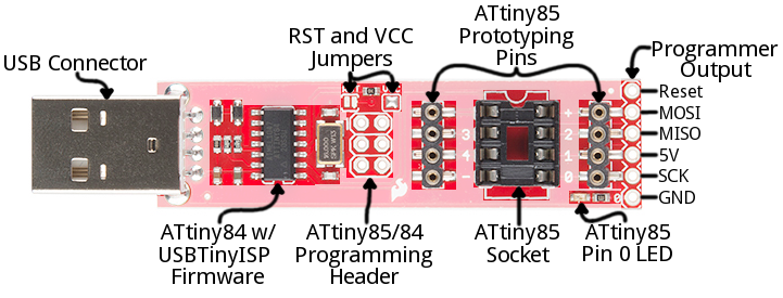
The "brain" of the Tiny AVR Programmer is an ATtiny84 (not to be confused with the 85), -- the 16-pin surface-mount chip -- which comes preprogrammed with some firmware that makes it look like an AVR programmer. Unless you're writing custom AVR ISP firmware, you shouldn't ever have to mess with this chip. It's a black box. Program data comes into it from your computer, over USB, and it spits out the proper sequence of bytes to load that program into your ATtiny85.
In this tutorial, we'll mostly concern ourselves with the components on the right half of the board. The ATtiny85 programming socket, pin 0 LED, and prototyping pins.
ATtiny85 Socket and Prototyping Pins
The socket and the pins broken out to the sides are what make the Tiny AVR Programmer unique. The 8-pin socket fits both the ATtiny85 and the ATtiny45 DIP packages. Just plug your IC-to-program into this socket, and a-programming you will go!
When plugging your ATtiny into the socket, take note of the notch on both the socket and the white silkscreen on the PCB. This should match the polarity of the ATtiny85. Usually the ATtiny85 has a dot next to pin 1 of the IC, this should be placed up towards the notch.
The +, -, and numerical labels on the side of the socket reference the pin numbers and voltage supply inputs of the ATtiny85. These pin numbers can be called in the Arduino IDE as we'll show later in this tutorial.
The 4-pin headers on either side of the socket help for prototyping the ATtiny85 out to external circuitry. You can easily plug male jumper wires into these pins, which can be routed to breadboards or other prototyping circuits.
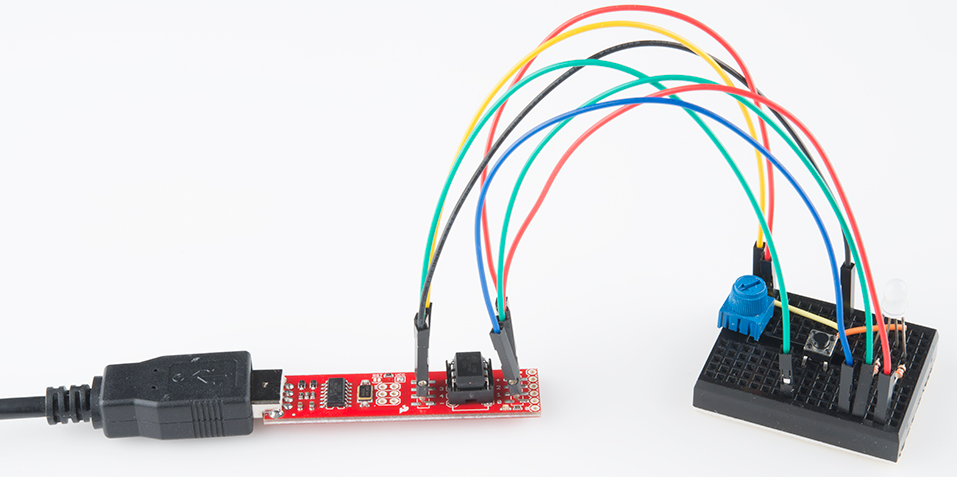
The 4-pin headers can also be used to connect to surface mount ATtiny85's or other AVR microcontrollers that are on breadboards.
Finally, there's an on-board amber LED connected to pin 0 of the ATtiny85. This is super-helpful when you're uploading the "Hello, world" blink sketch to an ATtiny85.
That covers the fundamental stuff on the Tiny AVR Programmer. If you plan on doing more advanced stuff with the board, or just want to know more, feel free to read on. Otherwise, skip ahead to the next page.
Output Programming Pins
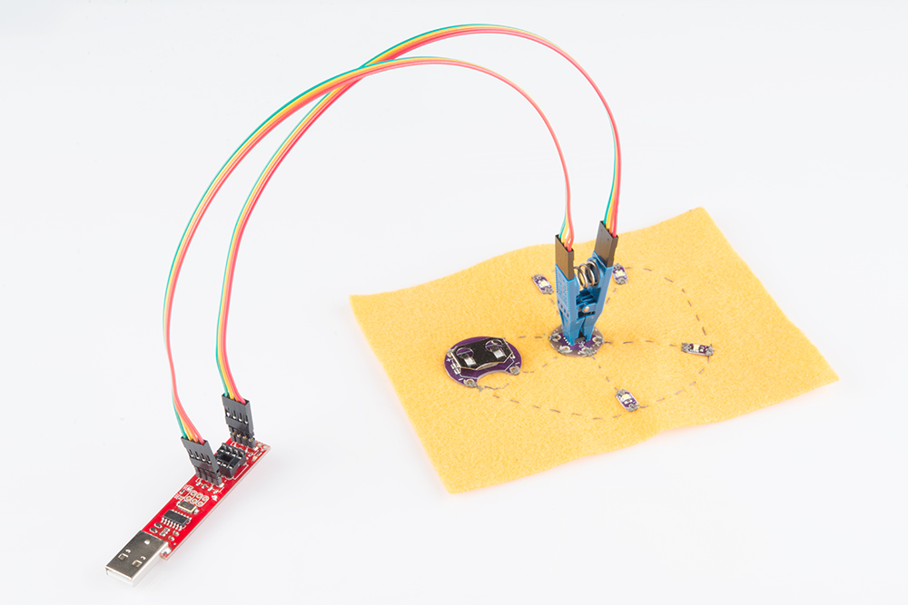
The Tiny ISP Programmer is not limited to ATtiny85's. It's a full-fledged AVR programmer. This row of six pins can be connected to other AVRs via the standard 2x3- or 2x5-pin ISP headers. You could, for example, connect these pins to your Arduino Uno, Leonardo, etc. to re-flash a bootloader, or upload code using a programmer.
Refer to the pin labels in the image above if you're connecting the Tiny AVR Programmer to another AVR chip. Most AVR development boards break out either a 2x3 or 2x5 programming header, which have the following pin-outs:
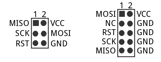
Just match up the labels on the Tiny Programmer to the pins on your AVR board/chip, and get ready to program!
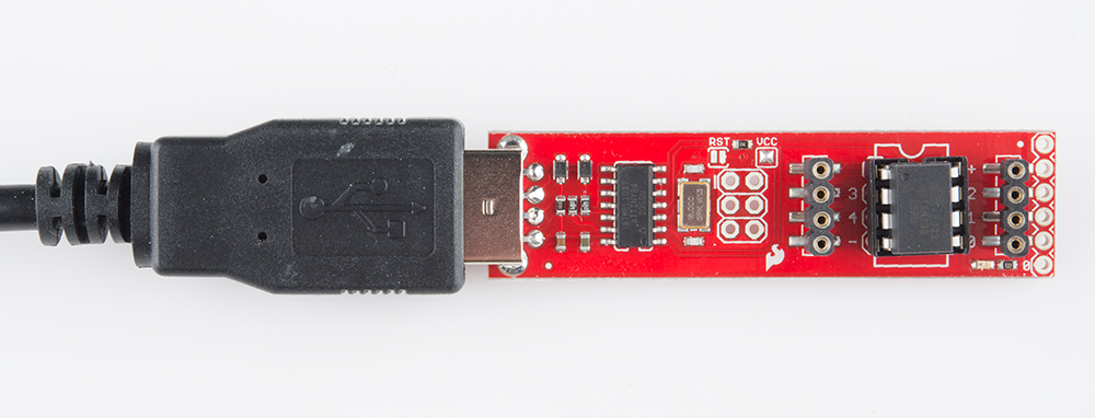
The Jumpers
There are two jumpers on the top side of the Tiny AVR Programmer: one is labeled RST and the other is VCC. Both of these jumpers affect the unpopulated 2x3 ICSP (in-circuit system programmer) header in the middle of the board. Unless you're planning on reprogramming the on-board ATtiny84, these jumpers and pins can generally be ignored.
The VCC jumper is normally closed. It controls the flow of power to the VCC pin on the ICSP header. When closed, power from USB will flow to the ICSP header. When open you'll need to supply power externally to that pin.
The RST jumper is normally open. When closed, this jumper connects the ATtiny84's reset pin to the to the 2x3 programming header. If you ever need to reprogram the ATtiny84 (which, for standard use cases, you shouldn't), you'll have to close this jumper to enable programming it.
Enough talk. Let's start using the programmer. On the next few pages we'll cover driver installation (for Windows users) and show how you can use the Tiny AVR Programmer to program an ATtiny85 in Arduino.