Transistors
 jimblom
Operation Modes
Unlike resistors, which enforce a linear relationship between voltage and current, transistors are non-linear devices. They have four distinct modes of operation, which describe the current flowing through them. (When we talk about current flow through a transistor, we usually mean current flowing from collector to emitter of an NPN.)
The four transistor operation modes are:
- Saturation -- The transistor acts like a short circuit. Current freely flows from collector to emitter.
- Cut-off -- The transistor acts like an open circuit. No current flows from collector to emitter.
- Active -- The current from collector to emitter is proportional to the base current.
- Reverse-Active -- Like active mode, the current is proportional to the base current, but it flows in reverse. Current flows from emitter to collector (not, exactly, the purpose transistors were designed for).
To determine which mode a transistor is in, we need to look at the voltages on each of the three pins, and how they relate to each other. The voltages from base to emitter (VBE), and the from base to collector (VBC) set the transistor's mode:
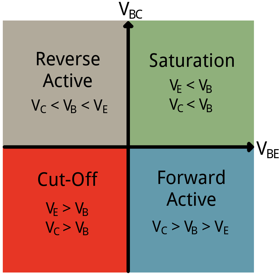
The simplified quadrant graph above shows how positive and negative voltages at those terminals affect the mode. In reality it's a bit more complicated than that.
Let's look at all four transistor modes individually; we'll investigate how to put the device into that mode, and what effect it has on current flow.
Note: The majority of this page focuses on NPN transistors. To understand how a PNP transistor works, simply flip the polarity or > and < signs.
Saturation Mode
Saturation is the on mode of a transistor. A transistor in saturation mode acts like a short circuit between collector and emitter.
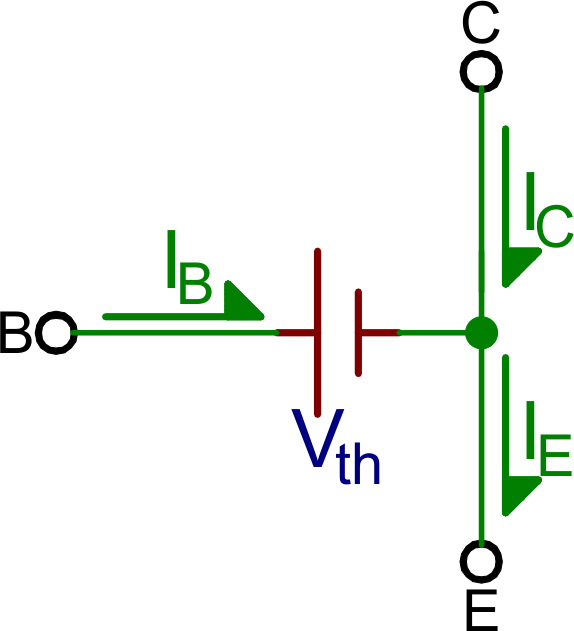
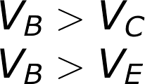
In saturation mode both of the "diodes" in the transistor are forward biased. That means VBE must be greater than 0, and so must VBC. In other words, VB must be higher than both VE and VC.
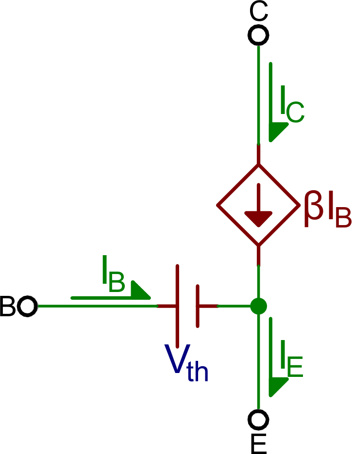
Because the junction from base to emitter looks just like a diode, in reality, VBE must be greater than a threshold voltage to enter saturation. There are many abbreviations for this voltage drop -- Vth, Vγ, and Vd are a few -- and the actual value varies between transistors (and even further by temperature). For a lot of transistors (at room temperature) we can estimate this drop to be about 0.6V.
Another reality bummer: there won't be perfect conduction between emitter and collector. A small voltage drop will form between those nodes. Transistor datasheets will define this voltage as CE saturation voltage VCE(sat) -- a voltage from collector to emitter required for saturation. This value is usually around 0.05-0.2V. This value means that VC must be slightly greater than VE (but both still less than VB) to get the transistor in saturation mode.
Cutoff Mode
Cutoff mode is the opposite of saturation. A transistor in cutoff mode is off -- there is no collector current, and therefore no emitter current. It almost looks like an open circuit.
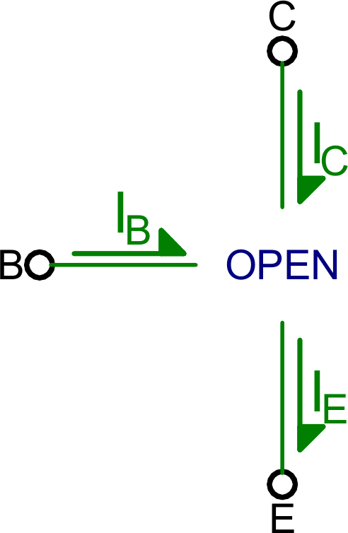
To get a transistor into cutoff mode, the base voltage must be less than both the emitter and collector voltages. VBC and VBE must both be negative.
In reality, VBE can be anywhere between 0V and Vth (~0.6V) to achieve cutoff mode.
Active Mode
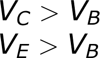
To operate in active mode, a transistor's VBE must be greater than zero and VBC must be negative. Thus, the base voltage must be less than the collector, but greater than the emitter. That also means the collector must be greater than the emitter.

In reality, we need a non-zero forward voltage drop (abbreviated either Vth, Vγ, or Vd) from base to emitter (VBE) to "turn on" the transistor. Usually this voltage is usually around 0.6V.
Amplifying in Active Mode
Active mode is the most powerful mode of the transistor because it turns the device into an amplifier. Current going into the base pin amplifies current going into the collector and out the emitter.
Our shorthand notation for the gain (amplification factor) of a transistor is β (you may also see it as βF, or hFE). β linearly relates the collector current (IC) to the base current (IB):

The actual value of β varies by transistor. It's usually around 100, but can range from 50 to 200...even 2000, depending on which transistor you're using and how much current is running through it. If your transistor had a β of 100, for example, that'd mean an input current of 1mA into the base could produce 100mA current through the collector.
What about the emitter current, IE? In active mode, the collector and base currents go into the device, and the IE comes out. To relate the emitter current to collector current, we have another constant value: α. α is the common-base current gain, it relates those currents as such:

α is usually very close to, but less than, 1. That means IC is very close to, but less than IE in active mode.
You can use β to calculate α, or vice-versa:
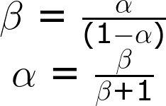
If β is 100, for example, that means α is 0.99. So, if IC is 100mA, for example, then IE is 101mA.
Reverse Active
Just as saturation is the opposite of cutoff, reverse active mode is the opposite of active mode. A transistor in reverse active mode conducts, even amplifies, but current flows in the opposite direction, from emitter to collector. The downside to reverse active mode is the β (βR in this case) is much smaller.
To put a transistor in reverse active mode, the emitter voltage must be greater than the base, which must be greater than the collector (VBE<0 and VBC>0).

Reverse active mode isn't usually a state in which you want to drive a transistor. It's good to know it's there, but it's rarely designed into an application.
Relating to the PNP
After everything we've talked about on this page, we've still only covered half of the BJT spectrum. What about PNP transistors? PNP's work a lot like the NPN's -- they have the same four modes -- but everything is turned around. To find out which mode a PNP transistor is in, reverse all of the < and > signs.
For example, to put a PNP into saturation VC and VE must be higher than VB. You pull the base low to turn the PNP on, and make it higher than the collector and emitter to turn it off. And, to put a PNP into active mode, VE must be at a higher voltage than VB, which must be higher than VC.
In summary:
| Voltage relations | NPN Mode | PNP Mode |
|---|---|---|
| VE < VB < VC | Active | Reverse |
| VE < VB > VC | Saturation | Cutoff |
| VE > VB < VC | Cutoff | Saturation |
| VE > VB > VC | Reverse | Active |
Another opposing characteristic of the NPNs and PNPs is the direction of current flow. In active and saturation modes, current in a PNP flows from emitter to collector. This means the emitter must generally be at a higher voltage than the collector.
If you're burnt out on conceptual stuff, take a trip to the next section. The best way to learn how a transistor works is to examine it in real-life circuits. Let's look at some applications!