Tsunami Super WAV Trigger Hookup Guide
Hardware Assembly
Basic Operation
The basic operation of the Qwiic Tsunami only requires the use of the trigger pins to interact with the board. For the example in the next section, users must insert their configured µSD card with *.wav files and connect their headphones to the Qwiic Tsunami.
Inserting the µSD Card
Inserting the µSD card, prepared from the previous section, is straight forward. The µSD card slot contains a spring-loaded locking mechanism:
- Insert the card and press in to lock the card into the slot.
- Press in to unlock and remove the card from the slot.
Connecting the Headphone Jack
Note: If users experience problems with the audio output to their headphones, there are different headphone connector standards that might be the issue. If that is the case, users only need to swap the connection from SLEEVE pin on TRRS 3.5mm breakout board to the RING2 pin.
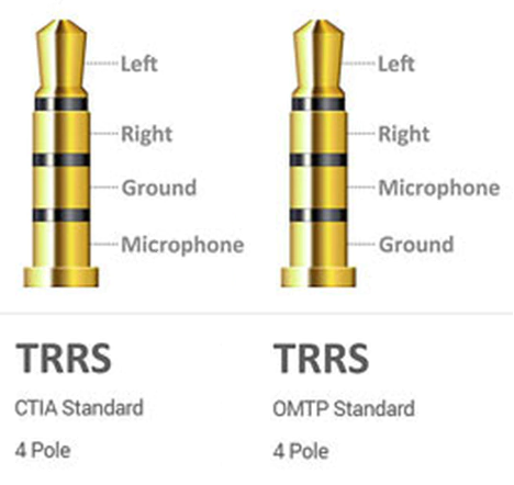
Two of the more common variations of the headphone jack connection standards. (Click to enlarge)
Source: quora.com
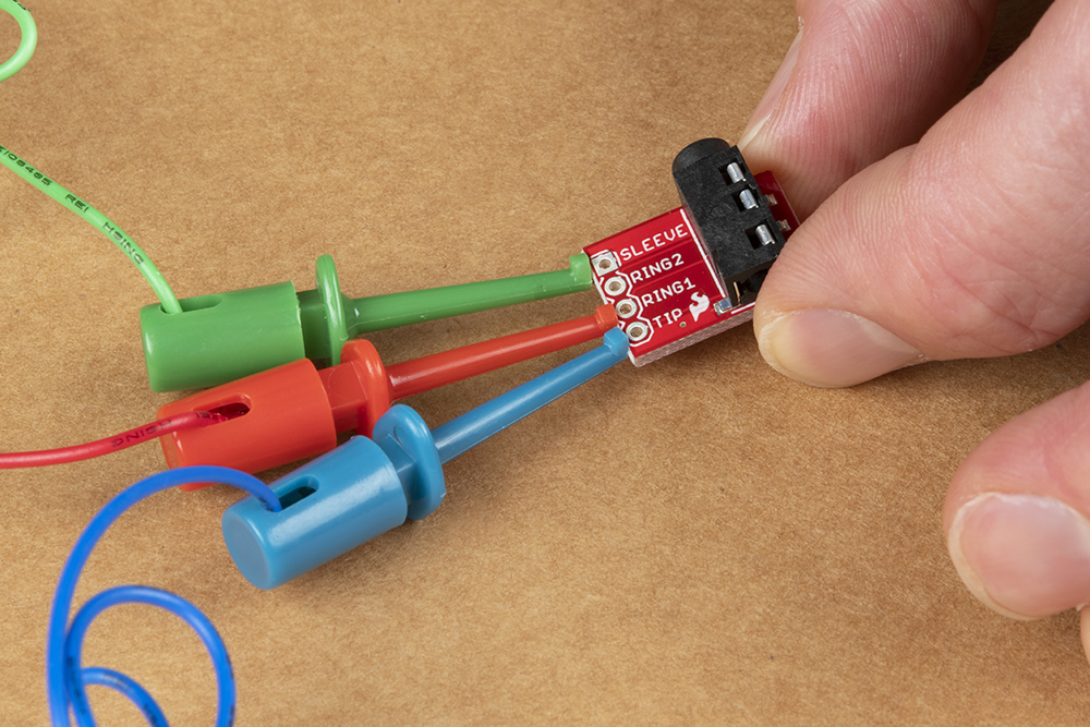
This part of the guide will demonstrate how to temporarily connect a pair of headphones to the audio output channels of the Qwiic Tsunami with the IC hook cables. Connect the TRRS 3.5mm jack breakout board to the Qwiic Tsunami, as illustrated below:
- Connect three of the IC hook cables to the
TIP,RING1, andSLEEVEpins on the TRRS headphone jack breakout board.
Attaching the IC hooks to the TRRS headphone jack breakout board. (Click to enlarge)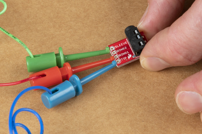
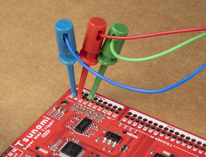
A close up of the IC hooks connected to the pins of the breakout board. (Click to enlarge) - Connect the other end of the cables to the
1L,1R, andGNDaudio output pins of the Qwiic Tsunami. Attaching the IC hooks to the audio output channels of the Qwiic Tsunami. (Click to enlarge)
Below, is a table summarizing the cable connections between the Qwiic Tsunami's pins and the TRRS 3.5mm jack breakout board's pins:
| Qwiic Tsunami | TRRS Breakout Board | |
|---|---|---|
| Cable 1 | 1L |
TIP |
| Cable 2 | 1R |
RING1 |
| Cable 3 | AGND |
SLEEVE |
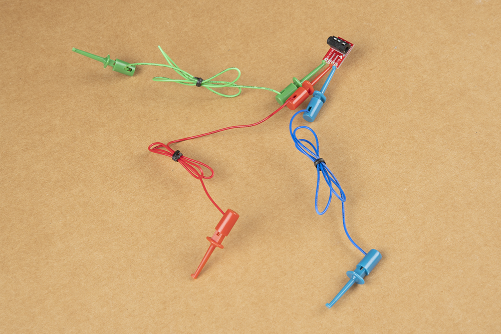
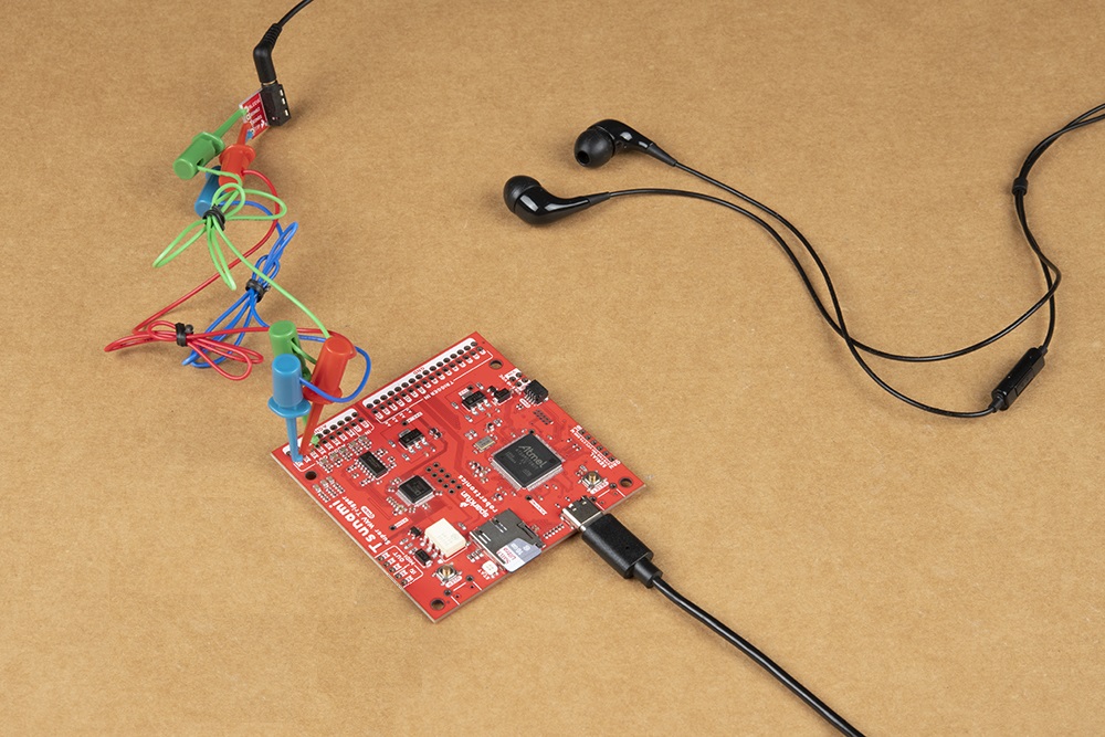
Finally, users will need to connect their headphones to the TRRS 3.5mm jack breakout board. The overall hardware assembly should resemble the image below:
For a more permanent solution, users can solder the boards together with hook-up wire.
Assembly for Arduino (Qwiic) Example
The assembly for the example in the Arduino library section is similar to the previous assembly. Users only need to connect their RedBoard Plus to the Qwiic Tsunami with a Qwiic cable. The RedBoard Plus should also be connected to their computer with a USB cable.

MIDI
Users interested in connecting the Qwiic Tsunami to other MIDI devices will need to solder the MIDI pins to a 5-pin DIN connector. For more information, users can check out the original Tsunami hookup guide, our MIDI tutorial, and the Tsunami user guide under "MIDI Implementation.
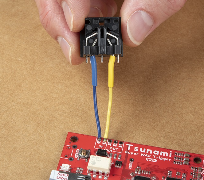
Attaching a MIDI connector to the Qwiic Tsunami. (Click to enlarge)
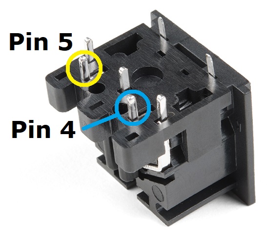
A close up of the MIDI connector pins. (Click to enlarge)