Tsunami Super WAV Trigger Hookup Guide
Hardware Overview
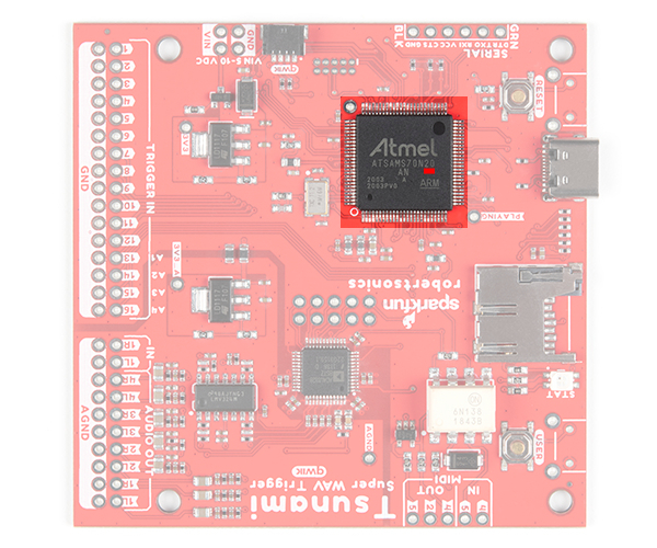
There are currently two versions: Tsunami Super WAV Trigger (Qwiic) and Tsunami Super WAV Trigger - 25 Voice (Qwiic). Both boards use the same PCB labeled as v21. To distinguish between the two, check out the label etched into the microcontroller: ATSAMS70N _ _, where the "_" denotes the different microcontroller that is populated on the board. The Tsunami Super WAV Trigger (Qwiic) uses the ATSAMS70N20 while the Tsunami Super WAV Trigger - 25 Voice (Qwiic) uses the ATSAMS70N19.
 |
 |
| ATSAMS70N20 Highlighted on the Tsunami Super WAV Trigger (Qwiic) - 32 Voices (Qwiic) |
ATSAMS70N19 Highlighted on the Tsunami Super WAV Trigger - 25 Voices (Qwiic) |
Power
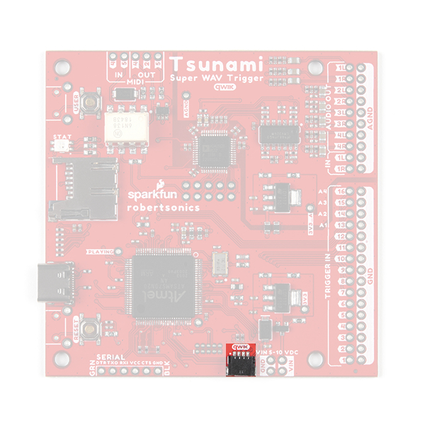
There is a status LED to help make sure that the Qwiic Tsunami is getting power. On the Qwiic Tsunami, users can power the board through either the USB-C connector or the power breakout pins (VIN and GND). We recommend users power the board through the USB-C connector.
The input voltage range for the power pins is 5V - 10V, but we recommend providing a 5V supply. The current draw from the Qwiic Tsunami is approximately 220mA (at 5V) at idle with an SD card inserted. When playing audio files, the current draw increases. (When testing, playing a single .wav file to a mono (single) channel output, the current draw spiked just past 240mA.)
By default, the board's power is isolated from the polarized Qwiic connector system. Although it isn't recommended, users can modify the 3V3_Qwiic jumper to draw power from the Qwiic connector (see jumper section below). The Qwiic system is meant to run on 3.3V, be sure that another voltage is NOT used with the Qwiic system.
Polyphonic Engine
The operation of the polyphonic engine on the Tsunami is proprietary to Robertsonics. While we can't go into exact details on how the board works, here are some highlights of the board:
- Supports up to 4096 uncompressed 16-bit, 44.1kHz mono or stereo WAV files – CD quality
- Polyphonic – Play and mix 32 mono or 18 stereo tracks independently and simultaneously
- Dynamic routing to 8 mono or 4 stereo outputs
- Seamless looping over arbitrary track length
- Independent real-time volume and playback rate control per output
- Pause and resume individual or groups of tracks
- Minimal trigger-to-sound delay: 8 msecs typ, 12 msecs max
- Trigger inputs can be individually inverted and set to be edge, latched, or level sensitive
- Dedicated MIDI I/O
- Assign individual MIDI notes to specific outputs, with individual looping control
- Outputs provide independent real-time playback rate control and MIDI Pitch Bend
- MIDI Velocity-sensitive triggering of up to 4096 tracks, adjustable attack and release times
- Line-level stereo audio input
- Output volumes adjustable from +10dB to -70dB
- Firmware track fades (attacks & decays)
- Extensive serial and I2C control (Default I2C address: 0x13)
- Reset button allows changing SD cards without power-cycle
- Firmware updates from µSD card. No additional hardware required
For more details, users can checkout the Tsunami product page on the Robertsonics website.
µSD Card Slot
- The 1GB SparkX SD Card, from our catalog, since it isn't a Class 10 card and can lead to reliability issues.
- SD Cards with a capacity larger than 32GB, since it can be difficult to convert them to the FAT16 or FAT32 file system format with a 32kB file allocation size.
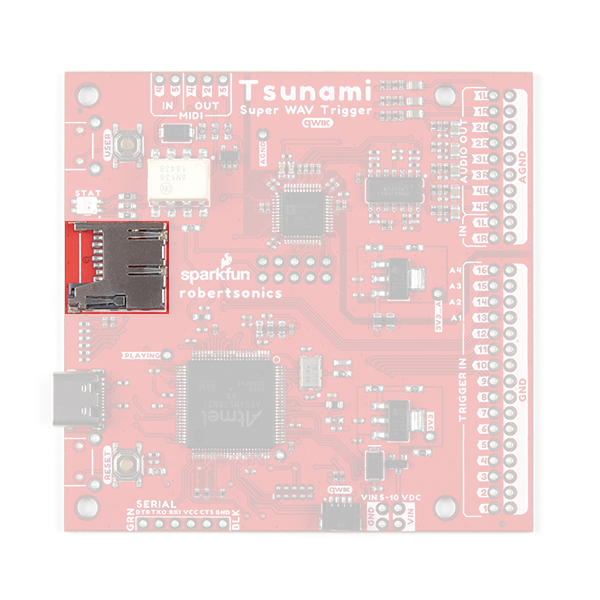
A µSD card is used store the audio *.wav files and initialization tsunami.ini file (optional) for the Qwiic Tsunami. The µSD card slot contains a spring-loaded locking mechanism:
- Insert the card and press in to lock the card into the slot.
- Press in to unlock and remove the card from the slot.
Buttons
There are two buttons available on the Qwiic Tsunami.
- RESET: Used to reset (reinitialize) the board after an SD card has been inserted.
- USER: Used to update the firmware from the SD card.
- Hold the USER button down
- Insert SD card with new firmware
tsunamix.hexfile (can have normal operation*.wavand*.inifiles) - Press RESET button
- Wait for successful firmware update status indicator before releasing the USER button
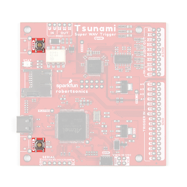
RESET and USER buttons on the Qwiic Tsunami. (Click to enlarge) Status LED
New on the Qwiic Tsunami is the RGB status indication LED.
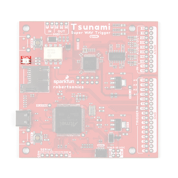
Along with this improvement is a whole list of status indicators for users:
- After SD card is inserted and Tsunami is reset:
- µSD card found and formatted correctly: 3 short green blinks, then idle state
- Error Codes:
- No µSD card: One long blue, then idle state
- µSD card format error (card installed but can't read FAT): One long red, one short, then idle state
- Audio hardware initialization error: One short red, repeats forever (continuous fast blinking red)
- During normal operation:
- System idle state: 1 very short blue (flash) every 3 seconds.
- Audio playing: Solid green.
- Error Codes:
- Stereo wave file is triggered with the mono firmware, or a mono wave file is triggered with the stereo firmware: 1 long red
- Bootloader operation (Updating firmware):
- Firmware successfully updated: Solid green
- Error Codes: (All bootloader blink codes, except success, repeat forever)
- No µSD card: One long blue, repeats (slow blinking blue.)
- µSD card format error (card installed but can't read FAT): One long red, one short red, repeats
- No firmware hex file found, or incorrect file contents: One long red, two short reds, repeats
- Flash write error (hardware error): One short red, repeats (fast blinking red.)
- Firmware successfully updated: Solid green.
Breakout Pins
There are a lot of breakout pins on the Qwiic Tsunami. While we won't cover them all, we'll discuss the pins with major functionality that users would normally interface with.
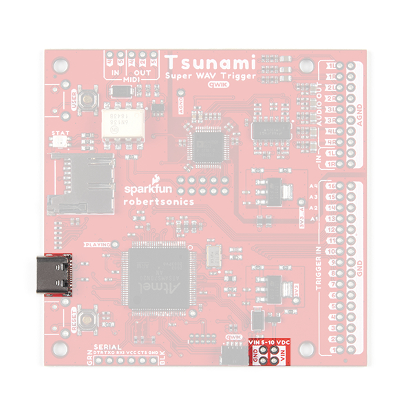
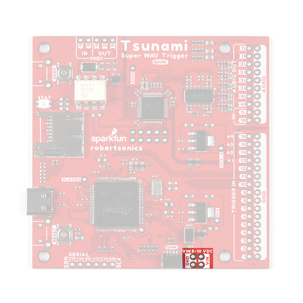
Power Input
While we normally recommend that users power the Qwiic Tsunami through the USB-C connector, there are four power input pins on the bottom of the board for users, who wish to permanently attach an external power source. The input voltage range is 5 - 10V, but we recommend providing a 5V supply.
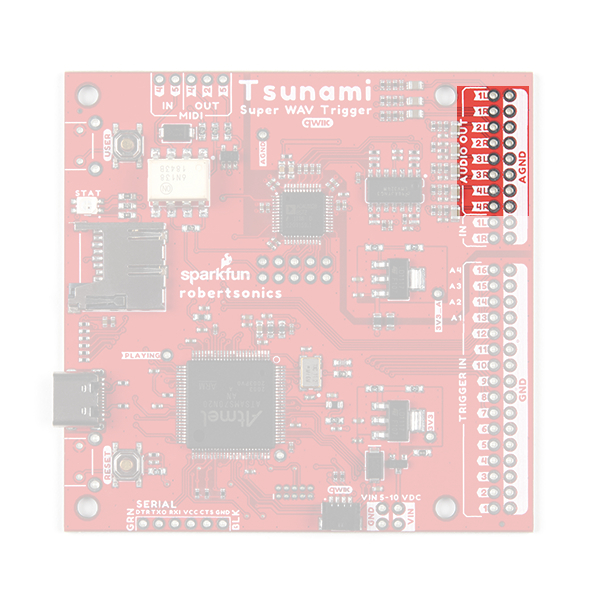
Audio Pins
The audio pins support up to 7.1 channel surround sound (or 8 mono channels) output and stereo (or 2 mono channels) line-level input.
Output Channels
For impedance matching the audio output channels, the impedance of the speakers or amplifiers should be above 3.8kΩ.
There is significant frequency roll off at the ends of the high and low range of the audio output channels. Extended use in these ranges can potentially damage the audio codec chip.
The audio output channels can be configured as stereo or mono outputs. By default, the factory programmed firmware on the Qwiic Tsunami only supports mono .wav file playback and audio output channels will act independently as eight mono outputs. For the best results, users should be hooking up the audio outputs to an amplifier or active speakers, which include an internal amplifier.
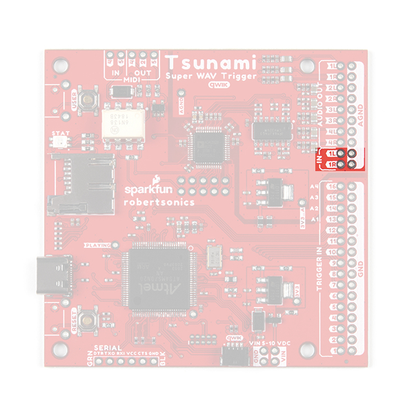
Input Channels
There are two line-level inputs on the Qwiic Tsunami. The inputs have capacitors to negate any DC offsets and are compatible with 1.1VPP signals.
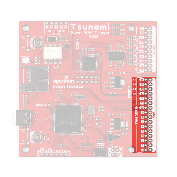
Trigger Pins
The trigger pins are the primary inputs for the Qwiic Tsunami. They can be configured to trigger various actions on the Qwiic Tsunami. By default, the 16 trigger pins are active-high and are triggered by pulling the pins low.
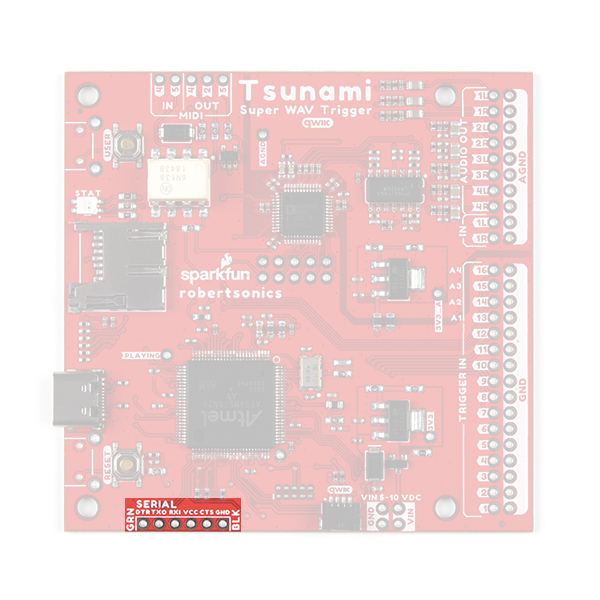
Serial Control
Users have the option of controlling the Qwiic Tsunami through the serial pins. Users can directly connect a USB-to-serial UART bridge like the Serial Basic Breakout or they can connect a microcontroller like the RedBoard Qwiic Plus.
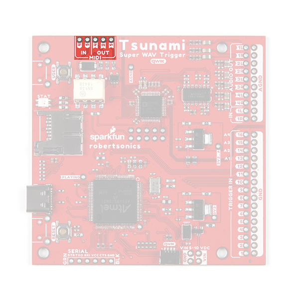
MIDI Pins
The Qwiic Tsunami can be connected with MIDI controllers and instruments; users only need to solder the pins to a 5-pin DIN connector. For more details, users can checkout the Tsunami User Guide and tutorial on the Robertsonics website.
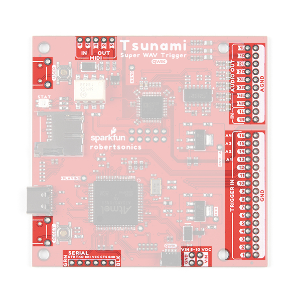
Buttons
There are two PTH breakouts for the two user buttons. These allow users to solder on their own right-angle buttons for a panel mounted operation.
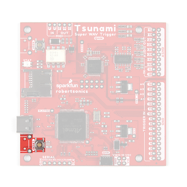
The reset breakout pins on the Qwiic Tsunami. (Click to enlarge)
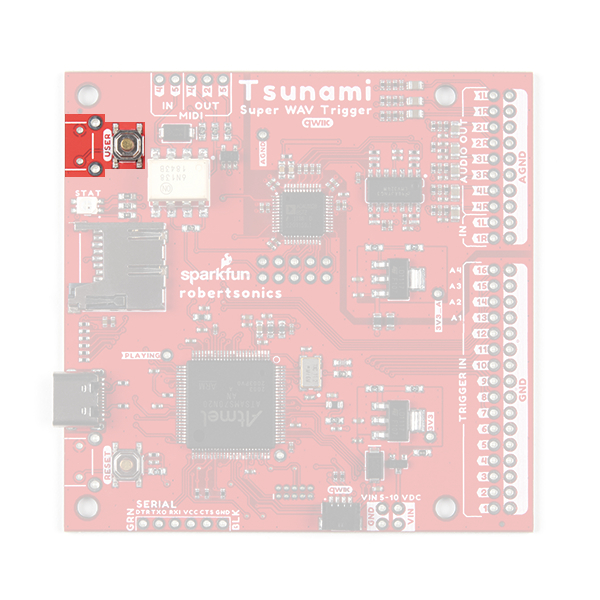
The user breakout pins on the Qwiic Tsunami. (Click to enlarge)
Qwiic Connector
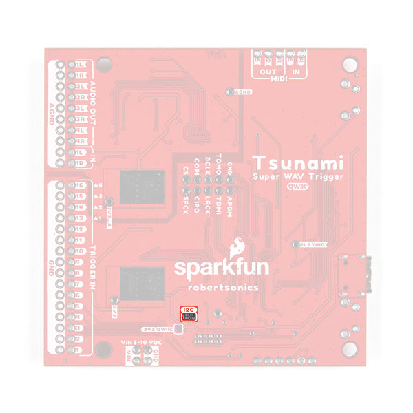
3V3 Qwiic jumper to draw power from the Qwiic connector. The Qwiic system is meant to run on 3.3V, be sure that another voltage is NOT used with the Qwiic system.New for the Qwiic Tsunami, users can now control the board through the an I2C protocol. The polarized Qwiic connector allows users to easily interface with the Qwiic connect system. The Qwiic Tsunami’s default I2C address is 0x13 (7-bit).
I2C Jumpers
There are two jumpers on the Qwiic Tsunami:
I2C3V3_Qwiic
Cutting the I2C jumper will remove the 2.2kΩ pull-up resistors from the I2C bus. If you have many devices on your I2C bus you may want to remove these jumpers.
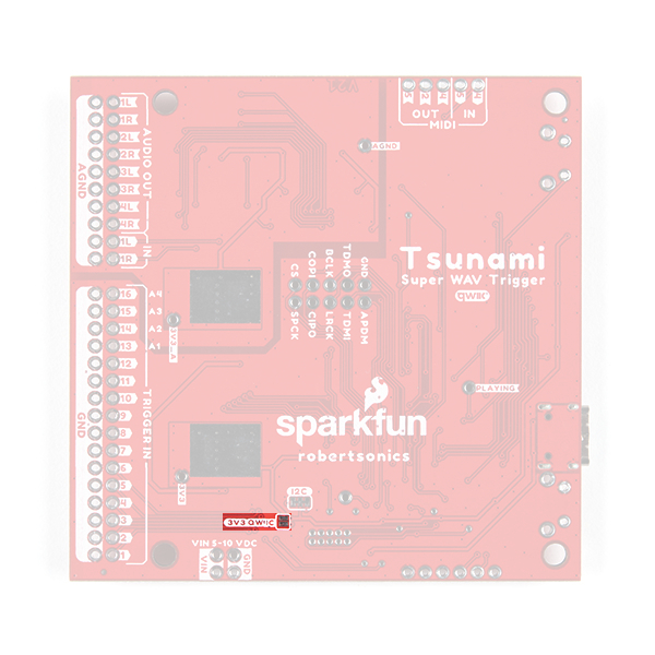
By default, the board's power is isolated from the Qwiic connector system. Bridging the 3V3_Qwiic jumper allows users to connect the board's power to the 3.3V input voltage of the Qwiic connect system.
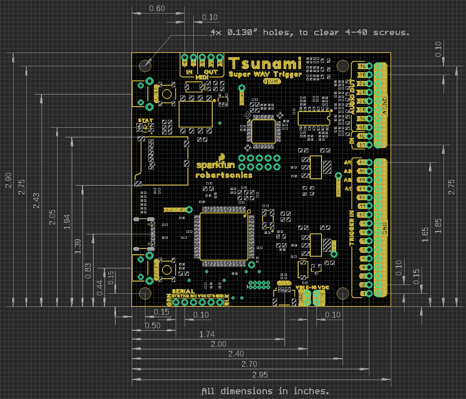
Board Dimensions
The dimensions for the Qwiic Tsunami are essentially the same as the original Tsunami. The overall board size is 2.95" x 2.925" (approx. 7.5cm x 7.4cm) and includes four 0.13" mounting holes, which are compatible with standard 4-40 screws.