Using EAGLE: Schematic
 jimblom
Adding Parts to a Schematic
Schematic design is a two step process. First you have to add all of the parts to the schematic sheet, then those parts need to be wired together. You can intermix the steps -- add a few parts, wire a few parts, then add some more -- but since we already have a reference design we'll just add everything in one swoop.
Using the ADD Tool
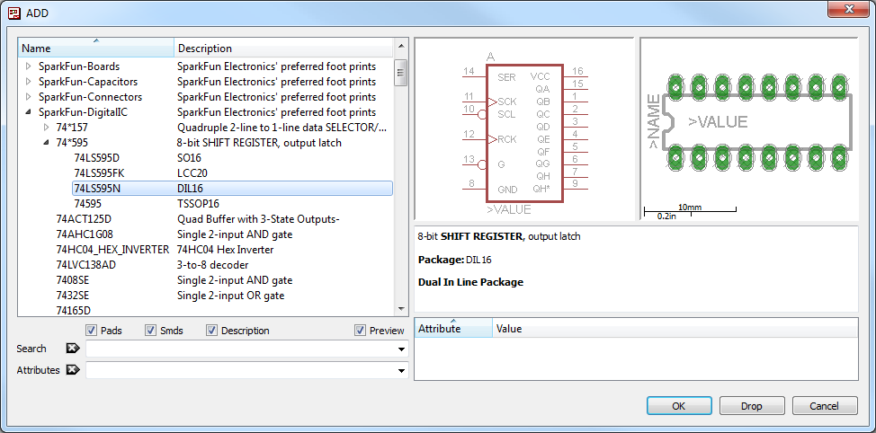
The ADD tool --  (on the left toolbar, or under the Edit menu) -- is what you'll use to place every single component on the schematic. The ADD tool opens up a library navigator, where you can expand specific libraries and look at the parts it holds. With a part selected on the left side, the view on the right half should update to show both the schematic symbol of the part and its package.
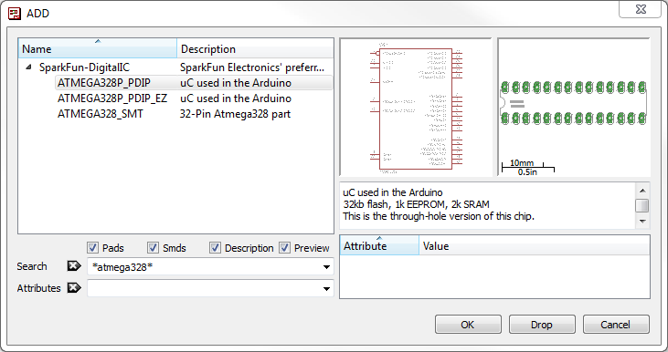
The ADD tool also has search functionality -- very helpful when you have to navigate through dozens of libraries to find a part. The search is very literal, so don't misspell stuff! You can add wildcards to your search by placing an asterisk (*) before and/or after your search term. For example if you search for atmega328 you should find a single part/package combo in the SparkFun-DigitalIC library, but if you search *atmega328* (note asterisks before and after), you'll discover two more versions of the IC (because they're actually named "ATMEGA328P"). You'll probably want to get accustomed to always adding an asterisk before and after your search term.
To actually add a part from a library either select the part you want and click "OK", or double-click your part.
Step 1: Add a Frame
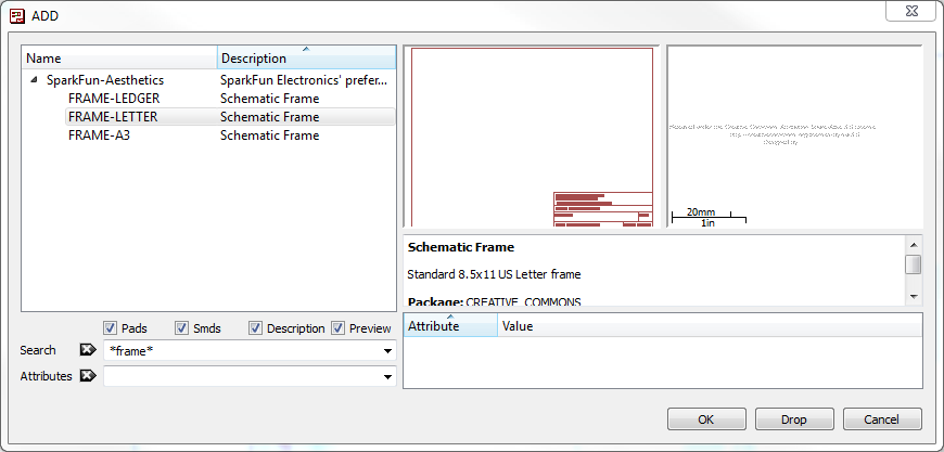
The frame isn't a critical component for what will be the final PCB layout, but it keeps your schematic looking clean and organized. The frame we want should be in the SparkFun-Aesthetics library, and it's named FRAME-LETTER. Find that by either searching or navigating and add it to your schematic.
After selecting the part you want to add, it'll "glow" and start hovering around following your mouse cursor. To place the part, left-click (once!). Let's place the frame so its bottom-left corner runs right over our origin (the small dotted cross, in a static spot on the schematic).

After placing a part, the add tool will assume you want to add another -- a new frame should start following your cursor. To get out of the add-mode either hit escape (ESC) twice or just select a different tool.
Step 2: Save (And Save Often)
Right now your schematic is an untitled temporary file living in your computer's ether. To save either go to File > Save, or just click the blue floppy disk icon --  . Name your schematic something descriptive. How about "BareBonesArduino.sch" (SCH is the file format for all EAGLE schematics).
As a bonus, after saving, your frame's title should update accordingly (you may have to move around the screen, or go to View > Redraw).
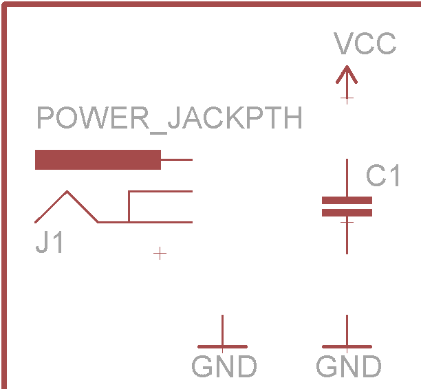
Step 3: Adding the Power Input
Next we'll add four different parts all devoted to our voltage supply input. Use the add tool for these parts:
| Part Description | Library | Part Name | Quantity |
|---|---|---|---|
| 5.5mm Barrel Jack (PTH) | SparkFun-Connectors | POWER_JACKPTH | 1 |
| 0.1µF Ceramic Capacitor | SparkFun-Capacitors | CAPPTH | 1 |
| Voltage Supply Symbol | SparkFun-Aesthetics | VCC | 1 |
| Ground Symbol | SparkFun-Aesthetics | GND | 2 |
All of these parts will go in the top-left of the schematic frame. Arranged like this:
If you need to move parts around, use the MOVE tool --  (left toolbar or under the Edit menu). Left-click once on a part to pick it up (your mouse should be hovering over the part's red "+" origin). Then left click again when it's where it needs to be.
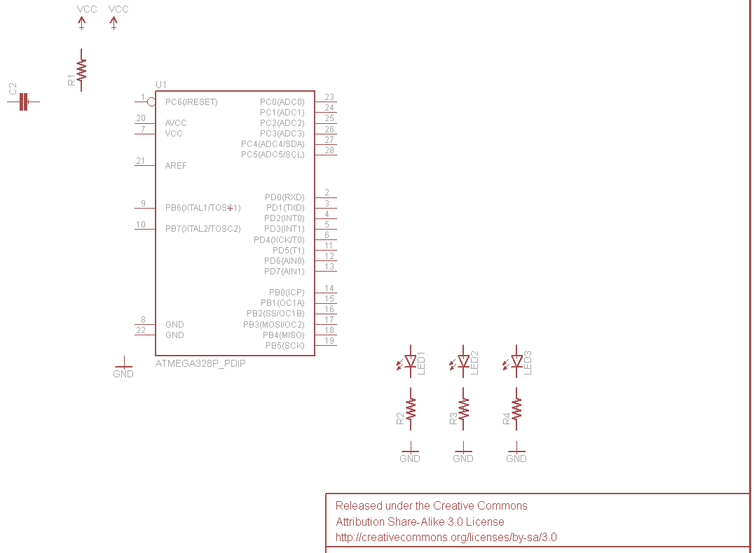
Step 4: Microprocessor and Supporting Circuitry
Next we'll add the main component of the design -- the ATmega328 microprocessor -- as well as some components to support it. Here are the parts we'll add:
| Part Description | Library | Exact Part Name | Quantity |
|---|---|---|---|
| ATmega328P (PTH) | SparkFun-DigitalIC | ATMEGA328P_PDIP | 1 |
| ¼W Resistors | SparkFun-Resistors | RESISTORPTH-1/4W | 4 |
| 5mm LEDs | SparkFun-LED | LED5MM | 3 |
| 0.1µF Ceramic Capacitor | SparkFun-Capacitors | CAPPTH | 1 |
| Voltage Supply Symbol | SparkFun-Aesthetics | VCC | 2 |
| Ground Symbol | SparkFun-Aesthetics | GND | 4 |
To rotate parts as your placing them, either select one of the four options on the rotate toolbar --  -- or right click before placing the part. Place your microcontroller in the center of the frame, then add the other parts around it like so:
Step 5: Adding the Connectors
Three connectors will finish off our design. One 8-pin connector to break out the analog pins, a 6-pin serial programming header, and a 2x3-pin ICSP programming header. Here are the three parts to add for this step:
| Part Description | Library | Exact Part Name | Quantity |
|---|---|---|---|
| 8-Pin 0.1" Header | SparkFun-Connectors | M081X08 | 1 |
| 2x3 AVR Programming Header | SparkFun-Connectors | AVR_SPI_PRG_6PTH | 1 |
| 6-Pin Serial Programming Header | SparkFun-Connectors | ARDUINO_SERIAL_PROGRAMPTH | 1 |
| Voltage Supply Symbol | SparkFun-Aesthetics | VCC | 2 |
| Ground Symbol | SparkFun-Aesthetics | GND | 2 |
Finally! Here's what your schematic should look like with every part added:
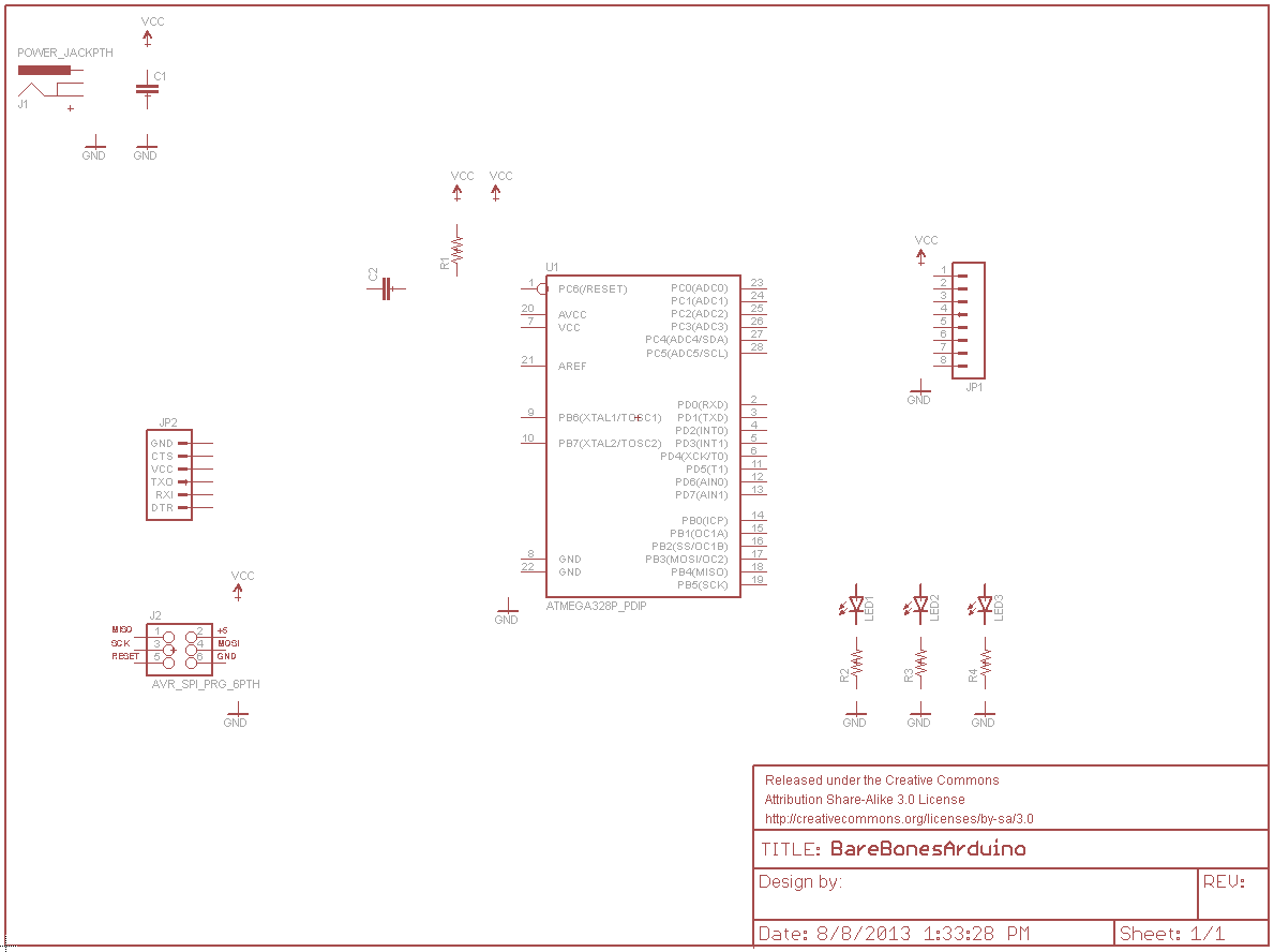
Next we'll wire net them all together.