Using the Arduino Pro Mini 3.3V
 jimblom
What It Is (and Isn't)
So what differentiates the Arduino Pro Mini from the Arduino Uno? Well, the most obvious difference is the form factor. The Pro Mini's pretty...mini, measuring in at just 1.3x0.70". It's about ⅙th the size of the Arduino Uno. The compact size is great for projects where you may need to fit the Arduino into a tiny enclosure, but it also means that the Pro Mini is not physically compatible with Arduino shields (you could still hard-wire the Mini up to any Arduino shield).
The Mini packs almost as much microprocessor-punch as the regular Arduino, but there are a few major hardware changes you should be aware of before you start adapting your project to the Mini. The first glaring hardware difference is the voltage that the Mini operates at: 3.3V. Unlike the Arduino Uno, which has both a 5V and 3.3V regulator on board, the Mini only has one regulator. This means that if you've got peripherals that only work at 5V, you might have to do some level shifting before you hook it up to the Pro Mini (or you could go for the 5V variant of the Pro Mini).
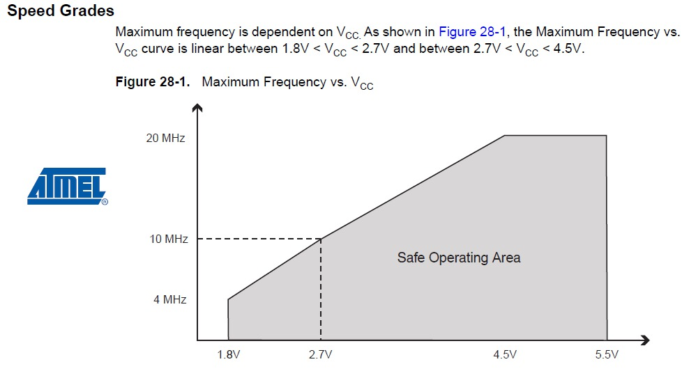
Another major variation from the standard Arduino lies in the speed at which the ATmega328 runs. The Pro Mini 3.3V runs at 8MHz, half the speed of an Arduino Uno. We put a slower resonator on the Mini to guarantee safe operation of the ATmega. That said, don't let the slower speed scare you away from using the Mini; 8MHz is still plenty fast, and the Mini will still be capable of controlling almost any project the Arduino Uno can.
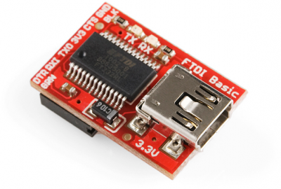
One last missing piece of hardware is the Atmega16U2-based USB-to-Serial converter, and the USB connector that goes with it. All of the USB circuitry had to be eliminated for us to make the Pro Mini as small as possible. The absence of this circuit means an external component, the FTDI Basic Breakout or any USB-to-serial converter, is required to upload code to the Arduino Pro Mini.
Schematic and Pin-out
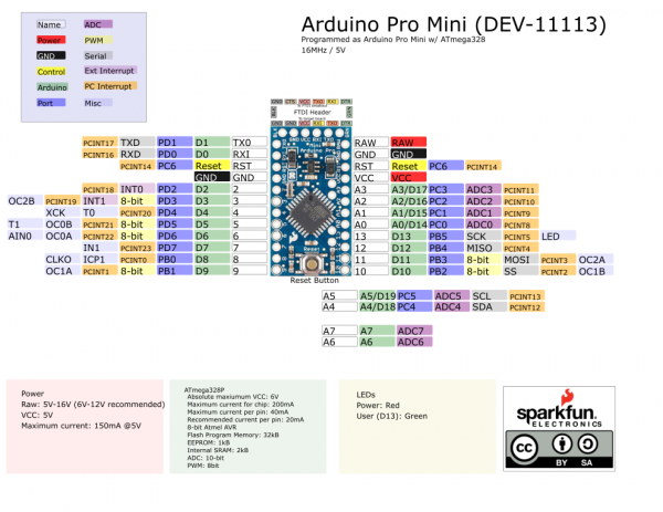
The schematic of the Pro Mini can be broken down into three blocks: the voltage regulator, the ATmega328 and supporting circuitry, and the headers.
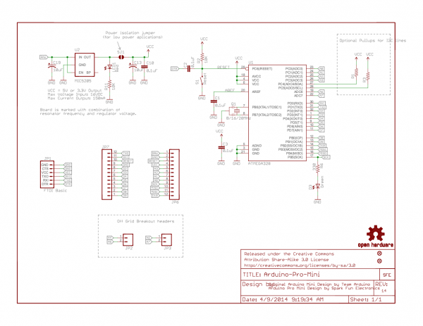
The Pro Mini's pins surround three of the four sides. The pins on the short side are used for programming, they match up to the FTDI Basic Breakout. The pins on the other two sides are an assortment of power and GPIO pins (just like the standard Arduino).
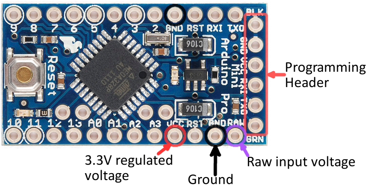
There are three different power-related pins: GND, VCC, and RAW. GND, obviously, is the common/ground/0V reference. RAW is the input voltage that runs into the regulator. The voltage at this input can be anywhere from 3.4 to 12V. The voltage at VCC is supplied directly to the Pro Mini, so any voltage applied to that pin should already be regulated to 3.3V.
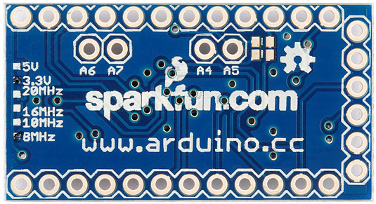
Four pins are actually not located on the edge of the board: A4, A5, A6 and A7. Each of these analog pins is labeled on the back side of the board.
A4 and A5's location may be very important if you plan on using I2C with the Pro Mini -- those are the hardware SDA and SCL pins.
More information about pins can be found in our graphical datasheets. The pinout listed on both datasheets are the same. The only difference is the voltage and frequency that the board operates at.
 |
 |
| Graphical Datasheet for the 5V/16Mhz Version | Graphical Datasheet for the 3.3V/8MHz Version |