Vernier Shield Hookup Guide
 bri_huang
Vernier Shield Pin-out and Configuration
Vernier standardized all of their sensors using a "standard" British Telecom connector. These connectors each have 6 wires that connect the sensor to the Vernier data collection interface. We designed the shield to maximize flexibility and ease-of-use for integrating up to two analog (BTA) and two digital (BTD) Vernier sensors to an Arduino. The full sensor pin-outs can be found on Vernier's site here.
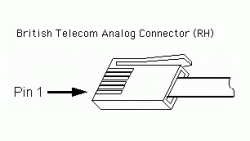
British Telecom Analog (BTA) – Right Hand
A large number of sensors used in the classroom fall under the category of "analog" sensors. Learn more about the differences between analog and digital here.
The pins of the BTA connector are defined as such:
| PIN # | Pin Name | Description
| 1
| Analog Sensor Output | (-10V to +10V) Used with a number of Vernier voltage probes. This is wired through a scale and shifting op-amp circuit so that the Arduino can read it on a scale of 0 - 5V.
| 2
| GND
| Ground.
| 3
| Vres
| Resistance reference. 15K pull-up resistor ties this pin to 5V to use as a voltage divider between Pin 6 and GND.
| 4*
| AutoIDENT
| Most sensors have a unique resistor that is tied between this pin and GND. Vernier uses this to identify the sensor. (not supported on all sensors)
| 5
| Power
| 5 VDC
| 6
| Analog Sensor Output | (0V to -5V) Primary sensor output for most analog sensors including light, temperature, force, pressure, pH, etc...
| |
http://www.vernier.com/support/sensor-pinouts/
To extend the use of Vernier equipment, they also offer a few voltage probes that allow for direct voltage measurements between +/- 6V, +/- 10V, and +/- 30V. On each of these probes, the signals are each tied to Pin 1 and and GND of the BTA connector.
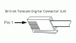
British Telecom Digital (BTD) – Left Hand
Digital sensors are any of the devices that return a signal that is either on (5V) or off (0V). Common digital sensors include: motion detector, photogate, radiation monitor, and the rotary motion sensors.
These sensors each have a somewhat unique pin-out definition. The following table outlines the pin assignments used for the Vernier digital connector.
Note that the connector is slightly different compared to the analog sensors. This is called a left-handed British Telecom connector and has the tab on the opposite side. The BTA and BTD connectors will not plug into the same socket.
| PIN # | DEFAULT | MOTION DETECTOR | PHOTOGATE | RADIATION MONITOR | ROTARY MOTION |
| 1 | IO1 | Echo | Input | Count | CCWcount |
| 2 | IO2 | Init | CWcount | ||
| 3 | IO3 | AutoIDENT | AutoIDENT | AutoIDENT | AutoIDENT |
| 4 | PWR | PWR | PWR | PWR | PWR |
| 5 | GND | GND | GND | GND | GND |
| 6 | IO4 | X4res |
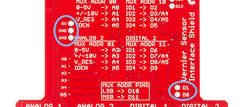
Arduino Shield Pin Assignments
To maximize the flexibility of using all of the Vernier sensors, we have made the following pin assignments on our shield. Many of the Vernier sensors use I2C for identification and calibration data. We use a multiplexer to "share" (multiplex) pins A4 and A5 between all four connectors. The multiplexer is controlled with Pins 10 (LSB) and Pin 11 (MSB). See the section on multiplexing for more information.
Pin assignments for analog ports
| Analog 1 | Analog 2 | Description | |
| MUX Control Address | 00 | 01 | Pins 10 (LSB) and 11 (MSB) control a multiplexer for A4 and A5. |
| Analog Signal (O - 5V) | A0 | A2 | Most analog sensors will interface to this pin. Use A0 for Analog 1 and A2 for Analog 2. |
| Analog Signal (-10V - +10V) | A1 | A3 | The shield has a built-in circuit to scale and shift input voltages from -10V to +10V to a range of 0V to 5V for pins A1 and A3. |
| V_res | A4* | A4* | Resistance reference. 15K pull-up resistor ties this pin to 5V to use as a voltage divider between Pin 6 and GND. |
| AutoIDEN | A5* | A5* | A 10K pull-up resistor ties these pins to 5V. The measured voltage drop across this pin uniquely identifies the sensor. |
Pin assignments for digital ports
| Digital 1 | Digital 2 | Description | |
| MUX Control Address | 10 | 11 | Pins 10 (LSB) and 11 (MSB) control a multiplexer for A4 and A5. |
| IO1 (BTD Pin 1) | 2 | 6 | Signal pin used for the photogate, motion detector echo, radiation count, and CCW rotary motion count. |
| IO2 (BTD Pin 2) | 3 / A4* | 7 / A4* | Trigger pin for the motion detector and I2C data (SDA) for sensor ID |
| IO3 (BTD Pin 3) | 4 / A5* | 8 / A5* | I2C clock (SCL) for sensor ID |
| IO4 (BTD Pin 6) | 5 | 9 | Used for rotary motion sensor to increase sensitivity. |
*Pins A4 and A5 are shared across all four connectors. In order to properly access the BTA and BTD connector pins, you will need to interface the analog multiplexer circuit.
Auxillary Pins and Connections
In addition to the internal wiring and routing for the Vernier BTA and BTD connectors, we placed an indicator LED tied to pin 13, a general purpose button on pin 12, and a reset button on the shield.
We also exposed vias for power and ground and pins 0 (RX) and 1 (TX) for adding serial communication peripherals like a Serial-enabled LCD or Serial 7-segment Display.