Voltage, Current, Resistance, and Ohm's Law
 CTaylor
An Ohm's Law Experiment
For this experiment, we want to use a 9 volt battery to power an LED. LEDs are fragile and can only have a certain amount of current flowing through them before they burn out. In the documentation for an LED, there will always be a "current rating". This is the maximum amount of current that can flow through the particular LED before it burns out.
Materials Required
In order to perform the experiments listed at the end of the tutorial, you will need:
- A multimeter
- A 9-Volt battery
- A 560-Ohm resistor(or the next closest value)
- An LED
NOTE: LEDs are what's known as a "non-ohmic" devices. This means that the equation for the current flowing through the LED itself is not as simple as V=IR. The LED introduces something called a "voltage drop" into the circuit, thus changing the amount of current running through it. However, in this experiment we are simply trying to protect the LED from over-current, so we will neglect the current characteristics of the LED and choose the resistor value using Ohm's Law in order to be sure that the current through the LED is safely under 20mA.
For this example, we have a 9 volt battery and a red LED with a current rating of 20 milliamps, or 0.020 amps. To be safe, we'd rather not drive the LED at its maximum current but rather its suggested current, which is listed on its datasheet as 18mA, or 0.018 amps. If we simply connect the LED directly to the battery, the values for Ohm's law look like this:


Dividing by zero gives us infinite current! Well, not infinite in practice, but as much current as the battery can deliver. Since we do NOT want that much current flowing through our LED, we're going to need a resistor. Our circuit should look like this:
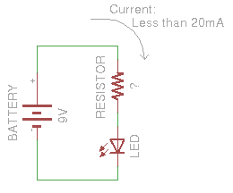
We can use Ohm's Law in the exact same way to determine the reistor value that will give us the desired current value:


So, we need a resistor value of around 500 ohms to keep the current through the LED under the maximum current rating.
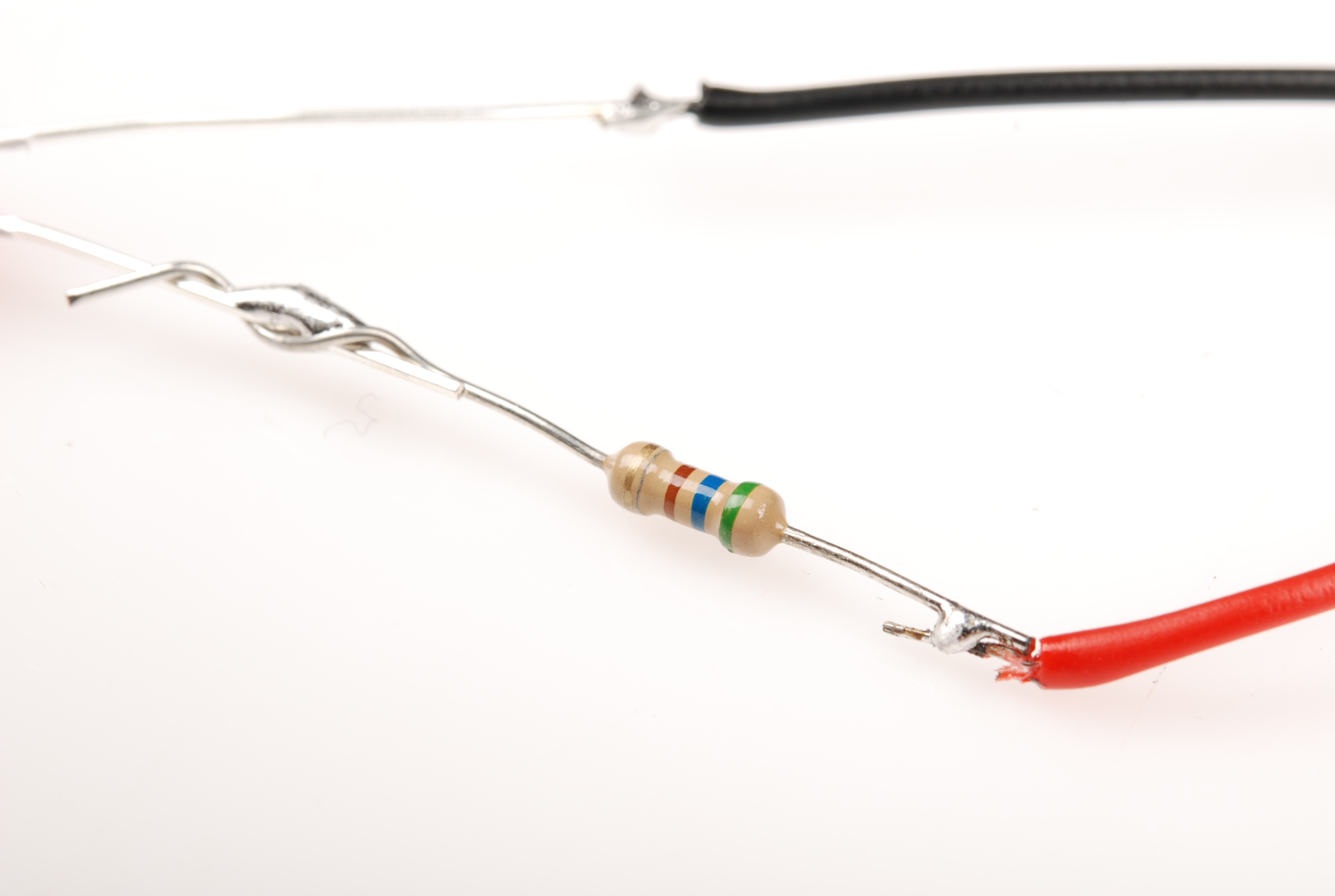
500 ohms is not a common value for off-the-shelf resistors, so this device uses a 560 ohm resistor in its place. Here's what our device looks like all put together.
Success! We've chosen a resistor value that is high enough to keep the current through the LED below its maximum rating, but low enough that the current is sufficient to keep the LED nice and bright.
This LED/current-limiting resistor example is a common occurrence in hobby electronics. You'll often need to use Ohm's Law to change the amount of current flowing through the circuit. Another example of this implementation is seen in the LilyPad LED boards.
With this setup, instead of having to choose the resistor for the LED, the resistor is already on-board with the LED so the current-limiting is accomplished without having to add a resistor by hand.
Current Limiting Before or After the LED?
To make things a little more complicated, you can place the current limiting resistor on either side of the LED, and it will work just the same!
Many folks learning electronics for the first time struggle with the idea that a current limiting resistor can live on either side of the LED and the circuit will still function as usual.
Imagine a river in a continuous loop, an infinite, circular, flowing river. If we were to place a dam in it, the entire river would stop flowing, not just one side. Now imagine we place a water wheel in the river which slows the flow of the river. It wouldn't matter where in the circle the water wheel is placed, it will still slow the flow on the entire river.
This is an oversimplification, as the current limiting resistor cannot be placed anywhere in the circuit; it can be placed on either side of the LED to perform its function.
For a more scientific answer, we turn to Kirchoff's Voltage Law. It is because of this law that the current limiting resistor can go on either side of the LED and still have the same effect. For more info and some practice problems using KVL, visit this website.