Wireless Arduino Programming with Electric Imp
 Nate
Nate 
Hardware Connections
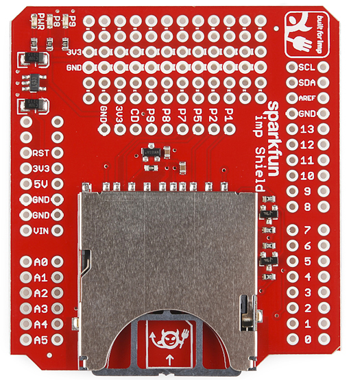
The very first step is to solder the Arduino headers to the Imp shield. For more information about how to do this, checkout this tutorial.
Next, we need to re-route the Imp's UART to the Arduino's serial pins (0 and 1). By default the Imp Shield connects the Imp's serial port (pins 5 and 7) to Arduino's pins 8 and 9.
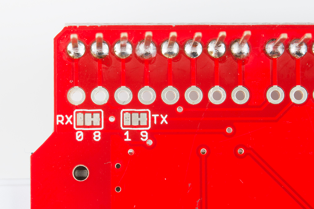
Luckily, the genius behind the Imp shield design had the foresight to make it easy to switch pins (Jim is awesome). On the back of the shield, you'll find two jumpers labeled RX and TX. In the image above, you should see a small trace connecting the TX and RX pins of the Imp to the right pads labeled 8 and 9.

Carefully use an exacto knife to cut the default trace. If you've never cut a trace before don't worry - it's easy! Just take your time. Cutting a trace is less like cutting through metal and more like scoring tile or scraping ice off your windshield; it takes a few passes. Once you've cut the traces, use a multimeter to do a continuity test to verify that you have indeed severed the connection between the center pad and the pad to the right.
Next, add some solder and jumper the center pads to their matching left pad. The Imp should now be wired directly to the Arduino's serial port.
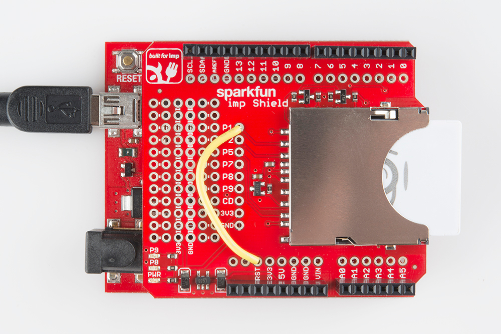
The final hardware modification is a jumper from P1 of the Imp to RST on the shield. This will allow the Imp to reset the Arduino whenever it pulls the P1 pin low.
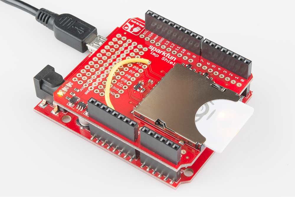
Once you've soldered the jumpers and single wire, add the Imp shield to your Arduino and connect a USB cable. Assuming you have commissioned your Imp to your local wifi, the Imp should power up, blink red, then blink green as it attaches to the Internet.
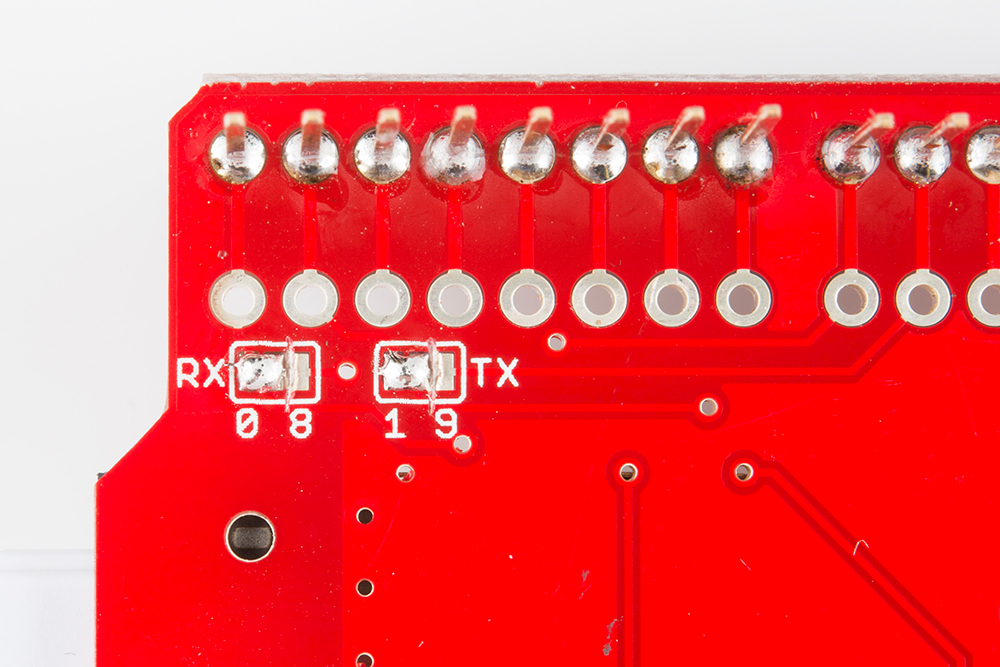
Now why did I tell you to take your time cutting the default traces? Because I made a big mistake when cutting the default TX trace. Have a second look:
Don't see the problem? How about now:
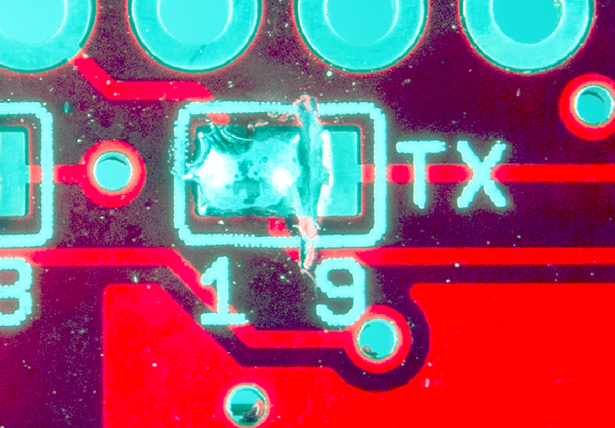
I was going too fast, the cut I made was too long, and I ended up cutting the TX trace to the Imp. When I attached everything to my Imp bootloading failed to work; everything was timing out because the Imp never heard a response from the Arduino (because the TX trace was cut). Luckily, I had a second functioning setup, so I tested my code on that. Everything worked, so I knew it must be a hardware problem with the board I was using for this tutorial. After a few minutes of scratching my head I used a multimeter to start probing for continuity. Once I discovered TX was not connected I tracked down this bad cut.
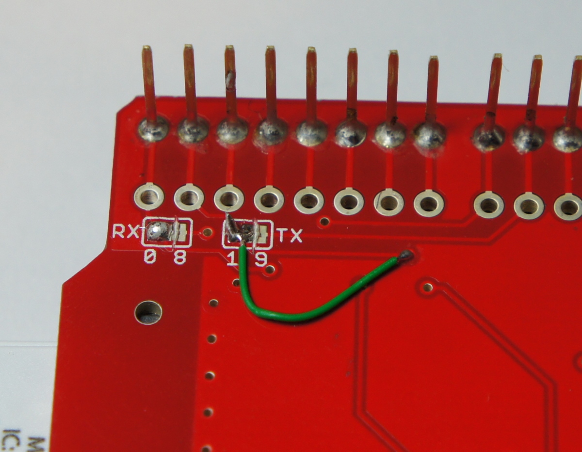
With some 30AWG wire wrap wire and some hemostats, the trace was quickly repaired, and the board started working as expected.
Take extra time when cutting traces so as to not cut beyond or knick nearby traces.