Wireless Glove Controller
 bboyho
 Introduction
In this tutorial, we will build a wireless glove controller with Arduino to trigger an LED remotely using XBees!
Required Materials
To follow along with this tutorial, you will need the following materials. You may not need everything though depending on what you have. Add it to your cart, read through the guide, and adjust the cart as necessary.
Tools
You will need wire, wire strippers, a soldering iron, solder, and general soldering accessories.


You Will Also Need
- Glove
- Scissors
- Non-Conductive Thread
- Tape
Suggested Reading
If you aren’t familiar with the following concepts, we recommend checking out these tutorials before continuing.
How to Solder: Through-Hole Soldering
LDK Experiment 5: Make Your Own Switch
XBee Shield Hookup Guide
Exploring XBees and XCTU
Understanding Your Circuit
Wireless Glove Controller
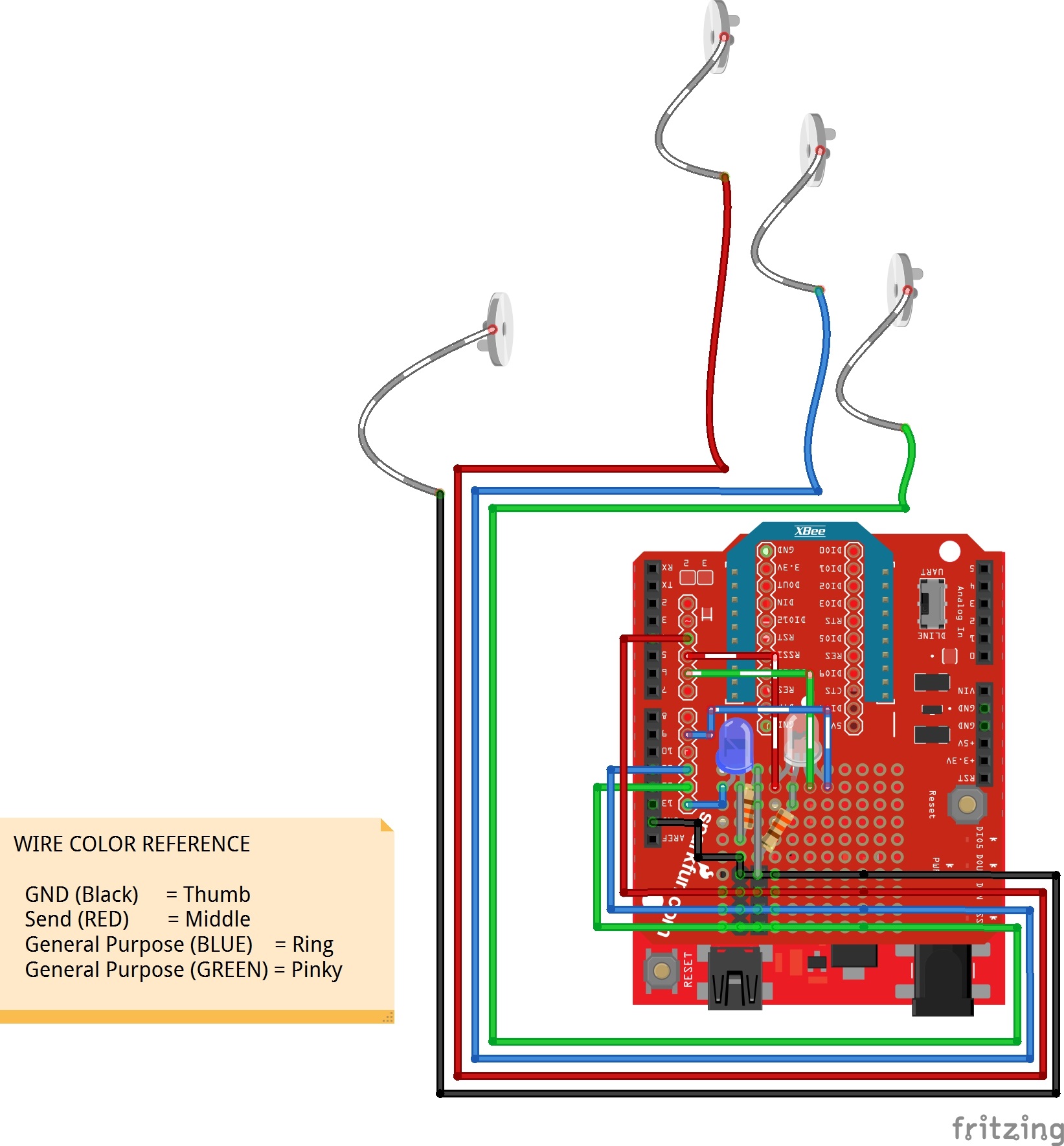
The simplest form of input is a button press, so we'll control LEDs remotely using buttons for this project as shown in the diagram below.
Custom Button
Since the electronics are going on a glove, the usual momentary button won't be the most comfortable on the fingers. Instead, we'll make our own custom button using snappable pins, conductive thread, and wire. You'll need to make a contact between your thumb, middle, ring, and pinky to GND, pin 4, pin 11, and pin 12, respectively.
LEDs
For feedback to indicate that we have sent a character wirelessly, we'll solder an LED and 330Ω current limiting resistor to the protoboard between pin 13 and ground. You could use the on-board LED on the RedBoard but it would be harder to see under the shield. Additionally, we'll attach a diffused, common cathode RGB LED to pins 5, 6, and 9. Make sure to add a second 330Ω current limiting resistor between the common cathode and GND, respectively.
Receiving XBee Node
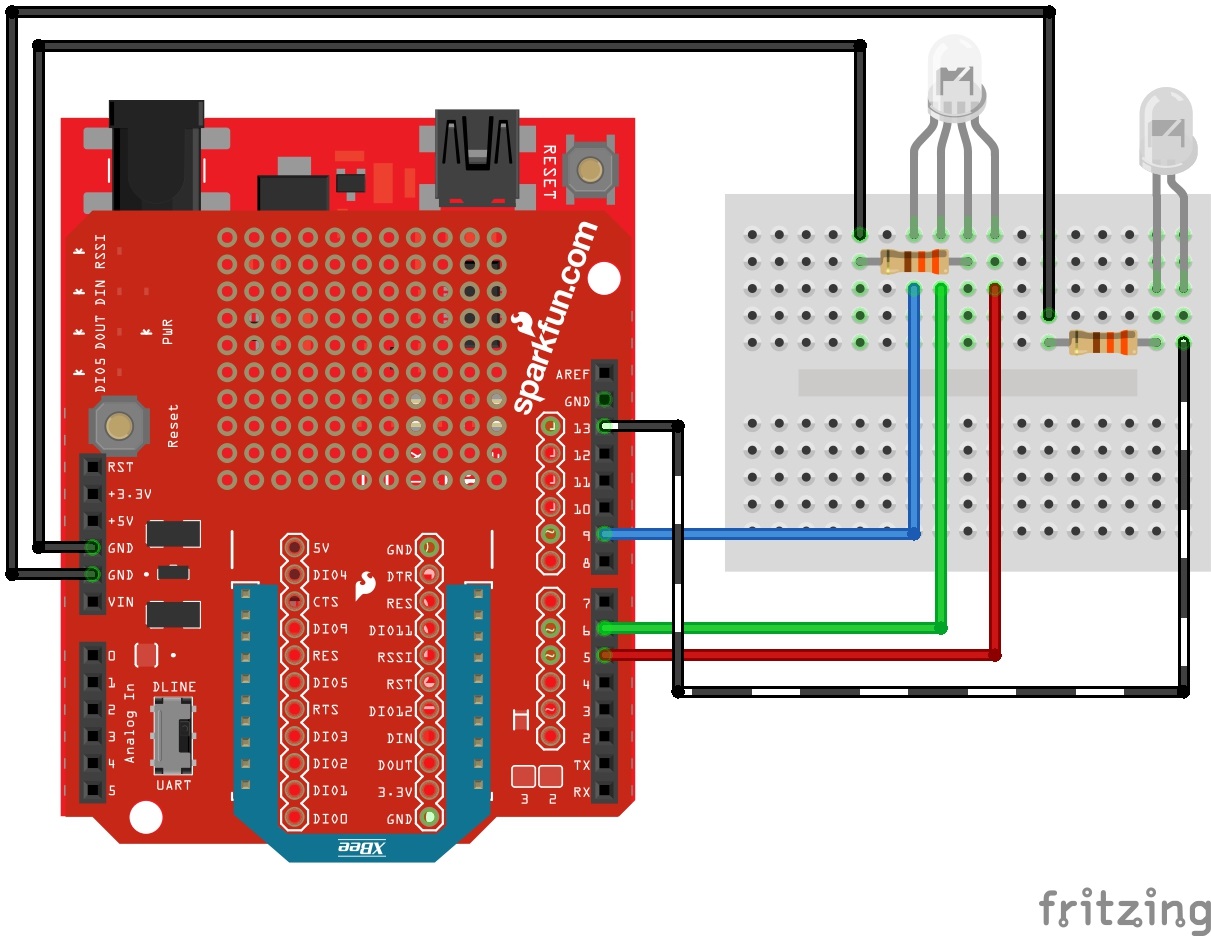
For the receiving XBee, we'll just mimic the LEDs used for feedback on the glove. The circuit is the same, that is without the custom buttons as shown in the diagram below. The board is flipped over to illustrate the receiving XBee node.
Hardware Hookup
Modify the XBee Shield
Using the circuit diagram from earlier, solder the components to the XBee shield. Then strip solid core hook-up wire and solder them between the pins. If you are following along, your board should look similar to the images below.
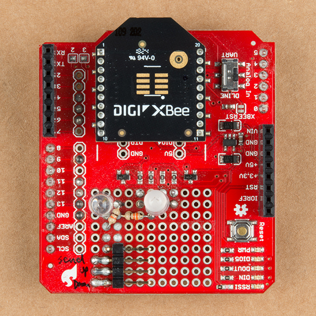 |
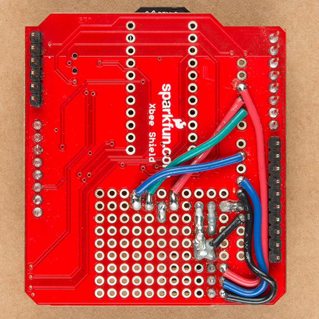 |
| Top View Components Soldered on XBee Shield | Bottom View with Wires and Jumpers |
Making a Connection Between Hard to Soft Materials
Grab four 12" F/F jumper wires of different colors and cut them in half. At this point, we'll need solder a wire loop from the standed wire so that we can easily connect the conductive thread to each of the finger's snappable pins. The other option is to thread the stranded wire through one of the holes on the snappable pin and solder them together.

Securing the Boards and Wires to the Glove
When you are finished, grab a needle, thread the non-conductive thread through the eye, and sew the RedBoard's mounting holes to the glove of your choice. I found that three of the holes was sufficient enough. Make sure to not sew the top and bottom of the glove together. Stack a configured XBee, XBee shield, and RedBoard together. Then insert the female housing into the right angle headers of the shield.
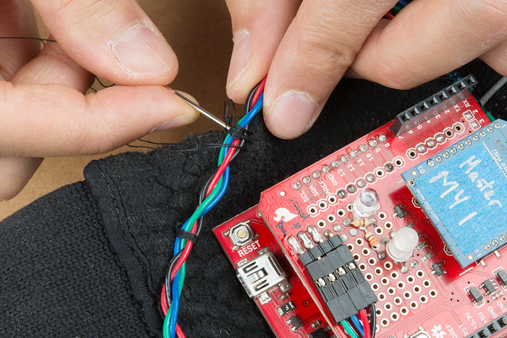
Braid the wires together and secure it to the glove using some non-conductive thread. For each wire, you will need to separate the wires as it gets closer to the fingers. Make sure there is enough space between the board and connections so that the board is not pressing against the wires. Test it out to ensure that there is enough tolerance so that the wires do not get damaged when the hand is moving.
Sewing the Custom Buttons
To make a connection to the snappable pins using conductive thread, we'll need to use a small needle. The two small needles provided in the needle set will be needed to sew the pin down. Find a spot for the snappable pin to make contact with the other finger. We'll start with the thumb. Grab the small needle, thread the conductive thread through the needle's eye, and sew the pin down. Sewing one of the four holes with conductive fabric should be sufficient enough if you loop it a few times. You could use non-conductive thread on the remaining holes. Again, avoid sewing the top and bottom fabric together.
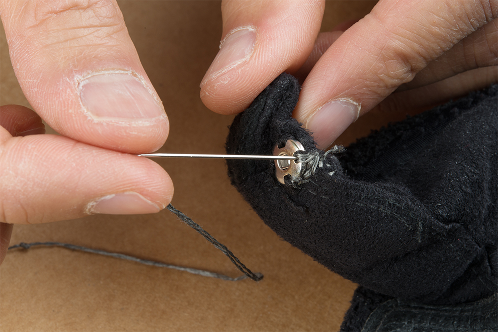
After a few loops around the the snappable pin's hole, make a running stitch to the top of the hand and make a connection to the wire loop to the respective pin connection. Following the circuit diagram, the thumb should be connected to the GND wire. Tie and cut off any excess thread.
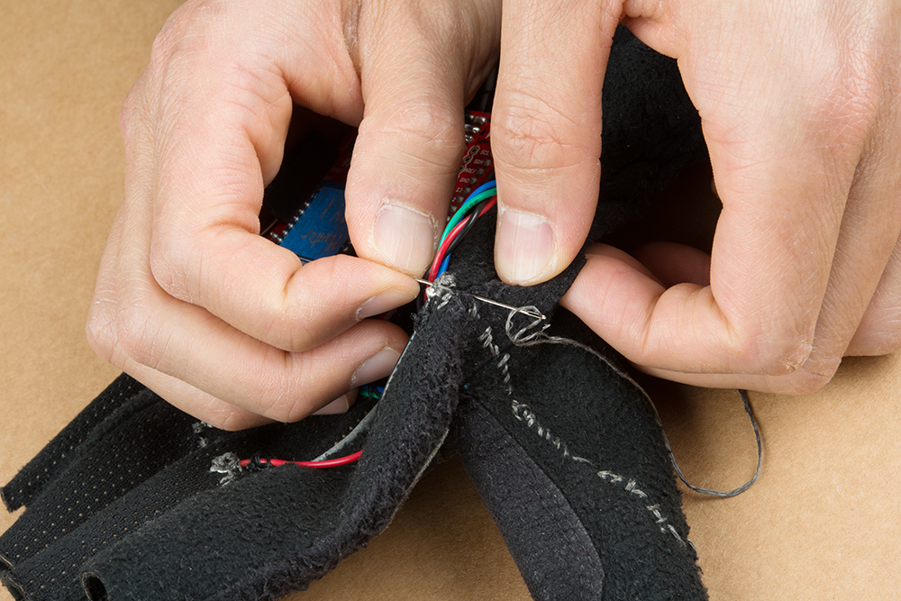
Repeat for each snappable pin.

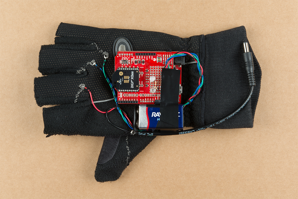
Assembled Wireless Glove Controller
When finished, your glove should look like the images below! Feel free to click on the images for a closer look.
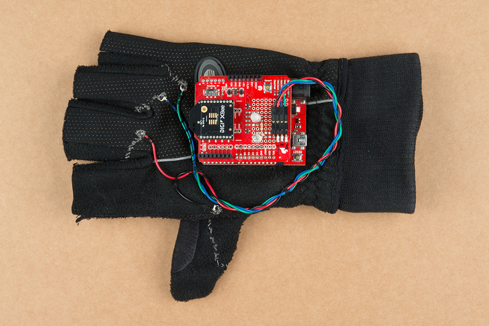 |
|
| Top View | Bottom View |
If you decide to use the glove remotely, add a 9V battery and secure it to the glove. In this case, electrical tape was used to hold the battery to the board. Feel free to sew together a 9V battery pouch to the glove for a more secure method.
Configuring XBees
To configure the XBees, we will be using the XBee Series 1 firmware. It is recommended to configure each XBee using the XBee Explorer USB.
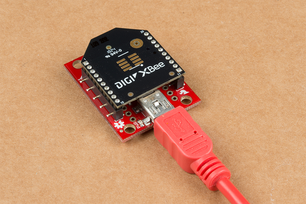
If you have not already, check out the Starting with XCTU section under Exploring XBees and XCTU to configure your XBees. If you are using an XBee 3, make sure to configure the firmware with the Series 1 firmware to follow along with this tutorial.
Exploring XBees and XCTU
March 12, 2015
Point-to-Point Configuration
For simplicity, we will be sending commands with the XBees in transparent mode set for a point-to-point configuration. Make sure to configure each XBee with a unique MY address if there are more than two XBees in your CH and PAN ID. You will then need to adjust the DL address for each respective XBee.
| Setting | Acronym | Transmitting XBee Node 1 (Wireless Glove Controller) | Receiving XBee Node 2 (i.e. LED/Robot/Dance Suit) |
|---|---|---|---|
| Channel | CH | C | C |
| PAN ID | ID | 3333 | 3333 |
| Destination Address High | DH | 0 | 0 |
| Destination Address Low | DL | 1 | 0 |
| 16-bit Source Address | MY | 0 | 1 |
Example 1: Sending and Receiving
If you've never connected an FTDI device to your computer before, you may need to install drivers for the USB-to-serial converter. Check out our How to Install FTDI Drivers tutorial for help with the installation.
Example 1a: Sending a Character with the Glove
In this part of the example, we'll have the glove send a character when a button is pressed. While you could just open a serial terminal to check if characters were received during testing, it would just not be as fun as blinking an LED wirelessly after a button press.
Copy the code, paste it into the Arduino IDE, select your board (Arduino/Genuino Uno), and COM port. Then upload the code to the glove.
language:c
// We'll use SoftwareSerial to communicate with the XBee:

#include <SoftwareSerial.h>

//For Atmega328P's
// XBee's DOUT (TX) is connected to pin 2 (Arduino's Software RX)
// XBee's DIN (RX) is connected to pin 3 (Arduino's Software TX)
SoftwareSerial XBee(2, 3); // RX, TX

//For Atmega2560, ATmega32U4, etc.
// XBee's DOUT (TX) is connected to pin 10 (Arduino's Software RX)
// XBee's DIN (RX) is connected to pin 11 (Arduino's Software TX)
//SoftwareSerial XBee(10, 11); // RX, TX


//Send
const int button1Pin = 4; //push button
const int status_LED = 13;  //LED on the push button

char send_CHAR = 'A'; //default send character

//initialize variables to read buttons
int button1State;

//variables to check for button1 state
boolean prev_button1State = false;
boolean current_button1State = false;

/*******************Setup Loop***************************/
void setup() {
  //Declare pin modes
  pinMode(button1Pin, INPUT_PULLUP); //use internal pullup resistor with send button
  pinMode (status_LED, OUTPUT);//LED to indicate when character has been sent

  //Status LED to see if the Transmitting XBee is initializing
  for (int i = 0; i < 3; i++) {
    digitalWrite(status_LED, HIGH);//set Status LED on
    delay(50);
    digitalWrite(status_LED, LOW); //set Status LED off
    delay(50);
  }

  //Declare serial connections for debugging
  Serial.begin(9600);
  Serial.println("Arduino Serial Ready");

  XBee.begin(9600);
  Serial.println("Glove Controller's XBee Ready to Communicate");

}//end setup()

void loop() {

  button1State = digitalRead(button1Pin);
  /***button1state
    - LOW or 0 means pressed
    - HIGH or 1 means not pressed
   ****/

  //if button is pressed, it will be pulled low
  if (button1State == LOW) {
    digitalWrite(status_LED, HIGH); //turn push button LED ON
    current_button1State = true; // button has been pressed once

    if (prev_button1State != current_button1State) //check to see if button is still being pressed
    {
      Serial.println("Button is pressed.");
      XBee.write(send_CHAR);//Sending a character
    }
    else {
      //do nothing because finger is still on button
    }
    prev_button1State = current_button1State;
  }

  //button has not been pressed, it will be high again
  else {
    current_button1State = false;
    digitalWrite(status_LED, LOW); // turn push button LED OFF

    prev_button1State = current_button1State;
  }
}//end loop()
Example 1b: Receiving XBee Node
In this part of the code, we'll have the receiving XBee blinking the LED connected to pin 13 as well. Copy the code below, paste it into the Arduino IDE, select your board (Arduino/Genuino Uno), and COM port. The Arduino should enumerate on a different COM port so make sure to adjust the COM port. Then upload the code to the receiving XBee's Arduino.
language:c

// We'll use SoftwareSerial to communicate with the XBee:

#include <SoftwareSerial.h>

//For Atmega328P's
// XBee's DOUT (TX) is connected to pin 2 (Arduino's Software RX)
// XBee's DIN (RX) is connected to pin 3 (Arduino's Software TX)
SoftwareSerial XBee(2, 3); // RX, TX

//For Atmega2560, ATmega32U4, etc.
// XBee's DOUT (TX) is connected to pin 10 (Arduino's Software RX)
// XBee's DIN (RX) is connected to pin 11 (Arduino's Software TX)
//SoftwareSerial XBee(10, 11); // RX, TX


//Declare character 'c_data'
char c_data;

//LED to check if the LED is initialized.
const int status_LED = 13;

/*******************Setup Loop***************************/
void setup() {
  // put your setup code here, to run once:

  //Declare pin modes
  pinMode (status_LED, OUTPUT);//LED to indicate when character has been sent

  //Status LED to see if the Receiving XBee is initializing
  for (int i = 0; i < 3; i++) {
    digitalWrite(status_LED, HIGH);//set Status LED on
    delay(50);
    digitalWrite(status_LED, LOW); //set Status LED off
    delay(50);
  }

  //Declare serial connections for debugging
  Serial.begin(9600);
  Serial.println("Arduino Serial Ready");

  XBee.begin(9600);
  Serial.println("XBee Ready to Receive");

}//end setup()

void loop() {

  //Check if XBee is receiving data from other XBee

  if (XBee.available() || Serial.available()) {
    if (XBee.available()) {
      c_data = XBee.read();//store received value from XBee into variable

    }

    else if (Serial.available()) {
      c_data = Serial.read();//store received value from Serial Monitor into variable

    }

    //Check to see if character sent is letter A
    if (c_data == 'A') {
      digitalWrite(status_LED, HIGH); //turn ON Status LED
      Serial.println("Character Received, ");
      Serial.println(c_data);
    }

    else {
      //do nothing
    }
  }
  delay(100);
  digitalWrite(status_LED, LOW); //turn OFF Status LED

}//end loop()
What You Should See
After uploading, touch the metal snap pins between your thumb and middle finger. This should send one character from the glove to the receiving XBee. As a result, the LED on the glove will stay on as long as the button is pressed. The receiving XBee's LED will blink whenever a character is received. As part of the design, we'll only send a character once when the button is pressed. To send another character, move your thumb away from the middle finger and then touch the metal snap pins together again.

Example 2: Controlling an RGB LED
Example 2a: RGB Wireless Glove Controller
We'll build on the first example and have the glove a send character to control an RGB LED. We'll use the snappable pins on the ring and pinky to switch between the colors.
Copy the code, paste it into the Arduino IDE, select your board (Arduino Uno), and COM port. Make sure to switch the COM port back what the glove enumerated to before uploading. When ready, upload the code to the glove.
language:c
// We'll use SoftwareSerial to communicate with the XBee:

#include <SoftwareSerial.h>

//For Atmega328P's
// XBee's DOUT (TX) is connected to pin 2 (Arduino's Software RX)
// XBee's DIN (RX) is connected to pin 3 (Arduino's Software TX)
SoftwareSerial XBee(2, 3); // RX, TX

//For Atmega2560, ATmega32U4, etc.
// XBee's DOUT (TX) is connected to pin 10 (Arduino's Software RX)
// XBee's DIN (RX) is connected to pin 11 (Arduino's Software TX)
//SoftwareSerial XBee(10, 11); // RX, TX


//SEND Button
const int button1Pin = 4; //push button
const int status_LED = 13;  //LED on the push button

char send_CHAR = 'A'; //default send character

//initialize variables to read buttons
int button1State;

//variables to check for button1 state
boolean prev_button1State = false;
boolean current_button1State = false;

//UP Button
const int button2Pin = 11; //push button

int button2State;
boolean prev_button2State = false;
boolean current_button2State = false;

//DOWN Button
const int button3Pin = 12;

int button3State;
boolean prev_button3State = false;
boolean current_button3State = false;

//LED Status Indicator
int ledR = 5;//hardware PWM
int ledG = 6;//hardware PWM
int ledB = 9; //hardware PWM

int pattern = 0; //pattern

/*******************Setup Loop***************************/
void setup() {

  //Declare pin modes
  pinMode(button1Pin, INPUT_PULLUP); //use internal pullup resistor with send button
  pinMode (status_LED, OUTPUT);//LED to indicate when character has been sent

  pinMode(button2Pin, INPUT_PULLUP); //use internal pullup resistor
  pinMode(button3Pin, INPUT_PULLUP); //use internal pullup resistor

  //Status LED to see if the Transmitting XBee is initializing
  for (int i = 0; i < 3; i++) {
    digitalWrite(status_LED, HIGH);//set Status LED on
    delay(50);
    digitalWrite(status_LED, LOW); //set Status LED off
    delay(50);
  }

  // initialize the digital pins as an output for LEDs
  pinMode(ledR, OUTPUT);
  pinMode(ledG, OUTPUT);
  pinMode(ledB, OUTPUT);

  sequenceTest();//visually initialization

  //Declare serial connections for debugging
  Serial.begin(9600);
  Serial.println("Arduino Serial Ready");

  XBee.begin(9600);
  Serial.println("Glove Controller's XBee Ready to Communicate");

}//end setup()

void loop() {

  button1State = digitalRead(button1Pin);
  button2State = digitalRead(button2Pin);
  button3State = digitalRead(button3Pin);
  /***buttonXstate
    - LOW or 0 means pressed
    - HIGH or 1 means not pressed
   ****/

  //-----------Check If SENT Button Has Been Pressed----------
  //if button is pressed, it will be pulled low
  if (button1State == LOW) {
    digitalWrite(status_LED, HIGH); //turn push button LED ON
    current_button1State = true; // button has been pressed once

    if (prev_button1State != current_button1State) //check to see if button is still being pressed
    {
      Serial.println("Button is pressed.");
      XBee.write(send_CHAR);//Tell Sequencer to change to mode by sending a character
    }
    else {
      //do nothing because finger is still on button
    }
    prev_button1State = current_button1State;
  }//-----------End Check for SENT Button----------

  //button has not been pressed, it will be high again
  else {
    current_button1State = false;
    digitalWrite(status_LED, LOW); // turn push button LED OFF

    prev_button1State = current_button1State;
  }//-----------End Check for SENT Button----------

  //-----------Check If UP Button Has Been Pressed----------
  if (button2State == LOW) {
    current_button2State = true; //UP button has been pressed once

    if (prev_button2State != current_button2State) { //check to see if button is still being pressed
      pattern = pattern + 1; //change LED pattern after button has been pressed
      if (pattern < 0 || pattern > 8) {
        //reset pattern
        pattern = 0;
      }

    }
    else { //do nothing because finger is still on button
    }
    prev_button2State = current_button2State;
  }
  //UP button has not been pressed, it will be high
  else {
    current_button2State = false;
    prev_button2State = current_button2State;
  }//-----------End Check for Up Button----------

  //-----------Check If DOWN Button Has Been Pressed----------
  if (button3State == LOW) {
    current_button3State = true; //button has been pressed once

    if (prev_button3State != current_button3State) { //check to see if button is still being pressed
      pattern = pattern - 1; //change LED pattern after button has been pressed
      if (pattern < 0 || pattern > 8) {
        //reset pattern
        pattern = 7;
      }
    }
    else { //do nothing because finger is still on button
    }
    prev_button3State = current_button3State;
  }
  //button has not been pressed, it will be high
  else {
    current_button3State = false;
    prev_button3State = current_button3State;
  }//-----------End Check for DOWN Button----------

  delay(50);

  //save send character into variable depending on button press and change status LED
  switch (pattern) {
    case 1:
      redON();
      delay(50);
      send_CHAR = 'B';
      break;
    case 2:
      magentaON();
      delay(50);
      send_CHAR = 'C';
      break;
    case 3:
      blueON();
      delay(50);
      send_CHAR = 'D';
      break;
    case 4:
      cyanON();
      delay(50);
      send_CHAR = 'E';
      break;
    case 5:
      greenON();
      delay(50);
      send_CHAR = 'F';
      break;
    case 6:
      yellowON();
      delay(50);
      send_CHAR = 'G';
      break;
    case 7:
      allOFF();
      delay(50);
      send_CHAR = 'H';
      break;
    default:
      allON();
      send_CHAR = 'A';
      break;
  }//end switch


}//end loop()

/*
  Check out the Venn Diagram on Basic Color Mixing:
  https://learn.sparkfun.com/tutorials/lilypad-protosnap-plus-activity-guide/2-basic-color-mixing

*/

void redON() {
  analogWrite(ledR, 255);
  analogWrite(ledG, 0);
  analogWrite(ledB, 0);
}

void magentaON() {
  analogWrite(ledR, 150);
  analogWrite(ledG, 0);
  analogWrite(ledB, 255);
}

void blueON() {
  analogWrite(ledR, 0);
  analogWrite(ledG, 0);
  analogWrite(ledB, 255);
}

void cyanON() {
  analogWrite(ledR, 0);
  analogWrite(ledG, 255);
  analogWrite(ledB, 255);
}

void greenON() {
  analogWrite(ledR, 0);
  analogWrite(ledG, 255);
  analogWrite(ledB, 0);
}

void yellowON() {
  analogWrite(ledR, 150);
  analogWrite(ledG, 255);
  analogWrite(ledB, 0);
}

void allOFF() {
  analogWrite(ledR, 0);
  analogWrite(ledG, 0);
  analogWrite(ledB, 0);
}

void allON() {//white
  analogWrite(ledR, 150);
  analogWrite(ledG, 255);
  analogWrite(ledB, 255);
}

void sequenceTest() {

  redON();
  delay(50);
  allOFF();
  delay(50);

  magentaON();
  delay(50);
  allOFF();
  delay(50);

  blueON();
  delay(50);
  allOFF();
  delay(50);

  cyanON();
  delay(50);
  allOFF();
  delay(50);

  greenON();
  delay(50);
  allOFF();
  delay(50);

  yellowON();
  delay(50);
  allOFF();
  delay(50);

  allON();
  delay(50);
  allOFF();
  delay(50);
}
Example 2b: RGB Receiving XBee Node
In this part of the example, we'll mimic the color being sent from the glove. Copy the code, paste it into the Arduino IDE, select your board (Arduino Uno), and COM port. Make sure to switch the COM port back to the receiving XBee's Arduino before uploading. When ready, upload the code to the receiving XBee's Arduino.
language:c
// We'll use SoftwareSerial to communicate with the XBee:

#include <SoftwareSerial.h>

//For Atmega328P's
// XBee's DOUT (TX) is connected to pin 2 (Arduino's Software RX)
// XBee's DIN (RX) is connected to pin 3 (Arduino's Software TX)
SoftwareSerial XBee(2, 3); // RX, TX

//For Atmega2560, ATmega32U4, etc.
// XBee's DOUT (TX) is connected to pin 10 (Arduino's Software RX)
// XBee's DIN (RX) is connected to pin 11 (Arduino's Software TX)
//SoftwareSerial XBee(10, 11); // RX, TX


//Declare character 'c_data'
char c_data;

//LED to check if the LED is initialized.
const int status_LED = 13;

//LED Status Indicator
int ledR = 5;//hardware PWM
int ledG = 6;//hardware PWM
int ledB = 9; //hardware PWM

/*******************Setup Loop***************************/
void setup() {
  // put your setup code here, to run once:

  //Declare pin modes
  pinMode (status_LED, OUTPUT);//LED to indicate when character has been sent

  //Status LED to see if the Receiving XBee is initializing
  for (int i = 0; i < 3; i++) {
    digitalWrite(status_LED, HIGH);//set Status LED on
    delay(50);
    digitalWrite(status_LED, LOW); //set Status LED off
    delay(50);
  }


  // initialize the digital pins as an output for LEDs
  pinMode(ledR, OUTPUT);
  pinMode(ledG, OUTPUT);
  pinMode(ledB, OUTPUT);

  sequenceTest();//visually initialization

  //Declare serial connections for debugging
  Serial.begin(9600);
  Serial.println("Arduino Serial Ready");

  XBee.begin(9600);
  Serial.println("XBee Ready to Receive");

}//end setup()

void loop() {

  //Check if XBee is receiving data from other XBee

  if (XBee.available() || Serial.available()) {
    if (XBee.available()) {
      c_data = XBee.read();//store received value from XBee into variable

    }

    else if (Serial.available()) {
      c_data = Serial.read();//store received value from Serial Monitor into variable

    }

    //Check to see if character sent is letter A
    if (c_data == 'A') {
      digitalWrite(status_LED, HIGH); //turn ON Status LED
      allON();
      Serial.println("Character Received, ");
      Serial.println(c_data);
    }

    else if (c_data == 'B') {
      digitalWrite(status_LED, HIGH); //turn ON Status LED
      redON();
      Serial.println("Character Received, ");
      Serial.println(c_data);
    }

    else if (c_data == 'C') {
      digitalWrite(status_LED, HIGH); //turn ON Status LED
      magentaON();
      Serial.println("Character Received, ");
      Serial.println(c_data);
    }

    else if (c_data == 'D') {
      digitalWrite(status_LED, HIGH); //turn ON Status LED
      blueON();
      Serial.println("Character Received, ");
      Serial.println(c_data);
    }

    else if (c_data == 'E') {
      digitalWrite(status_LED, HIGH); //turn ON Status LED
      cyanON();
      Serial.println("Character Received, ");
      Serial.println(c_data);
    }
    else if (c_data == 'F') {
      digitalWrite(status_LED, HIGH); //turn ON Status LED
      greenON();
      Serial.println("Character Received, ");
      Serial.println(c_data);
    }
    else if (c_data == 'G') {
      digitalWrite(status_LED, HIGH); //turn ON Status LED
      yellowON();
      Serial.println("Character Received, ");
      Serial.println(c_data);
    }
    else if (c_data == 'H') {
      digitalWrite(status_LED, HIGH); //turn ON Status LED
      allOFF();
      Serial.println("Character Received, ");
      Serial.println(c_data);
    }
    else {
      //do nothing
    }
  }

  delay(100);
  digitalWrite(status_LED, LOW); //turn OFF Status LED

}//end loop()

/*
  Check out the Venn Diagram on Basic Color Mixing:
  https://learn.sparkfun.com/tutorials/lilypad-protosnap-plus-activity-guide/2-basic-color-mixing

*/

void redON() {
  analogWrite(ledR, 255);
  analogWrite(ledG, 0);
  analogWrite(ledB, 0);
}

void magentaON() {
  analogWrite(ledR, 150);
  analogWrite(ledG, 0);
  analogWrite(ledB, 255);
}

void blueON() {
  analogWrite(ledR, 0);
  analogWrite(ledG, 0);
  analogWrite(ledB, 255);
}

void cyanON() {
  analogWrite(ledR, 0);
  analogWrite(ledG, 255);
  analogWrite(ledB, 255);
}

void greenON() {
  analogWrite(ledR, 0);
  analogWrite(ledG, 255);
  analogWrite(ledB, 0);
}

void yellowON() {
  analogWrite(ledR, 150);
  analogWrite(ledG, 255);
  analogWrite(ledB, 0);
}

void allOFF() {
  analogWrite(ledR, 0);
  analogWrite(ledG, 0);
  analogWrite(ledB, 0);
}

void allON() {//white
  analogWrite(ledR, 150);
  analogWrite(ledG, 255);
  analogWrite(ledB, 255);
}

void sequenceTest() {

  redON();
  delay(50);
  allOFF();
  delay(50);

  magentaON();
  delay(50);
  allOFF();
  delay(50);

  blueON();
  delay(50);
  allOFF();
  delay(50);

  cyanON();
  delay(50);
  allOFF();
  delay(50);

  greenON();
  delay(50);
  allOFF();
  delay(50);

  yellowON();
  delay(50);
  allOFF();
  delay(50);

  allON();
  delay(50);
  allOFF();
  delay(50);
}
What You Should See
By using the thumb to make contact with either the ring and pinky's snappable pin, the RGB LED will switch between colors. Pressing on the thumb and middle finger will send a character associated with the RGB LED. The receiving XBee should mimic the color of the RGB LED whenever a character is sent.
Resources and Going Further
Need some inspiration for your next project? Check out some of these related tutorials to add more functionality for your wireless glove!
Flex Sensor Hookup Guide
LilyPad Vibe Board Hookup Guide
Qwiic Flex Glove Controller Hookup Guide
Wireless Gesture Controlled Robot
Looking for more examples of data gloves? Check out the various gloves from Kobakant.
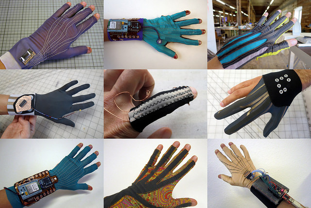 |
| Various E-Textile Data Glove Projects Courtesy of Kobakant |
Or check out some of these blog posts for ideas: