Wireless RC Robot with Arduino and XBees
 bboyho
Experiment 4: Wirelessly Triggering Audio
Introduction
Remember making sounds with the RedBot? In this section, we'll wirelessly control the buzzer to make a familiar sound.
Parts Needed
You will need the following parts from the required materials:
- 2x XBees (Configured to Series 1 Firmware)
- 1x Cerberus Cable (or 1x micro-B USB and 1x mini-B USB Cable)
- 1x Assembled Shadow Chassis w/ RedBot Mainboard
- 1x Piezo Buzzer
- 4x AA Batteries
- 1x Assembled Wireless Joystick
- 1x LiPo Battery
4.1: Adding Audio Commands w/ the SAMD21
For this part of the experiment, we will add a few commands to trigger a familiar sound.
Hardware Hookup
If you have not already, insert the XBee and battery into the controller. Then connect the controller to your computer via USB cable.

Open the Sketch
Copy and paste the following code into the Arduino IDE. Remember to select the SAMD21 DEV Breakout for the controller, select the COM port that it enumerated on, flip the Wireless Joystick's switch to the ON position, and hit upload.
language:c
/* 4_1_Full_Remote_Control_SAMD_Audio.ino
   Full Remote Control SAMD21 Example with Buzzer
   Written by: Ho Yun Bobby Chan
   Date: 2/15/19
   SparkFun Electronics

   license: Creative Commons Attribution-ShareAlike 4.0 (CC BY-SA 4.0)
   Do whatever you'd like with this code, use it for any purpose.
   Please attribute and keep this license.

   This is example code for the Wireless Joystick with SAMD21. Any character entered through the
   Serial Monitor or when a condition statement is satisfied will be sent to the hardware UART pins.
   Assuming that you have a pair of XBees Series 1 modules (or Series 3 modules configured with 802.15.4 protocol) on the
   same channel, a character will be transmitted wirelessly between the XBees. The receiving
   XBee will then pass the character to the an ATmega328P microcontroller to move the robot forward.

   Pressing down on D2 (if you soldered the joystick on the right or a button) will check
   the joystick on the left. A character will be transmitted when moving the joystick.

       up = forward
       right = forward turn right
       down = reverse
       left = forward turn left
       center = coast

   When D2 is not being pressed, a character will be sent to stop the motors.

   Pressing down on D6 (left trigger) or D3 (right trigger) will send another character

       left trigger = coin
       right trigger = fireball

   The RedBot will need to be programmed to read those values.

   Note: You may need to connect A5 to the XBee Series 3's reset pin on the Wireless Joystick
   for certain XBee Series 3 modules. For more details, check out the xbee3_RESET() function.
*/

#define L_TRIG 6        // Pin used for left trigger
#define R_TRIG 3        // Pin used for right trigger
boolean prev_buttonL_State = HIGH;    //value to store the previous state of the button press
boolean current_buttonL_State = HIGH; //value to store the current state of the button press

boolean prev_buttonR_State = HIGH;    //value to store the previous state of the button press
boolean current_buttonR_State = HIGH; //value to store the current state of the button press

#define FORWARD_REVERSE_JOYSTICK A3   // Pin used for left joystick's y-component
#define TURN_JOYSTICK A2   // Pin used for left joystick x-component

boolean current_buttonACCELERATE_State;
#define ACCELERATE_BUTTON 2 // Pin used for right trigger

// We'll store the the analog joystick values here
int16_t forward_reverse_Stick_value;
int16_t turnStick_value;

char c_data;//send values through the serial monitor for debugging

//LED to check if the LED is initialized.
const int status_LED = 13;

//needed for certain XBee Series 3 modules
#define xbee_reset A5

void setup() {

  pinMode(L_TRIG, INPUT_PULLUP); // Enable pullup resistor for left trigger
  pinMode(R_TRIG, INPUT_PULLUP); // Enable pullup resistor for right trigger

  SerialUSB.begin(9600);// Initialize Serial Monitor for DEBUGGING

  //Uncomment this if you want to wait until the serial monitor is open.
  //while (!SerialUSB); //Wait for Serial Monitor to Open

  SerialUSB.println("Wireless Joystick Controller Initializing");
  Serial1.begin(9600); // Start serial communication with XBee at 9600 baud

  xbee3_RESET();//in case XBee3 has issues initializing, hardware reset

  pinMode(ACCELERATE_BUTTON, INPUT_PULLUP); // Enable pullup resistor for accelerate button D2

  //Status LED to see if the Controller is initializing
  pinMode(status_LED, OUTPUT);
  for (int i = 0; i < 3; i++) {
    digitalWrite(status_LED, HIGH);//set Status LED on
    delay(50);
    digitalWrite(status_LED, LOW); //set Status LED off
    delay(50);
  }
  SerialUSB.println("Wireless Joystick Controller's XBee Ready to Communicate");
  delay(10);
}//end setup

void loop() {

  current_buttonL_State = digitalRead(L_TRIG);
  current_buttonR_State = digitalRead(R_TRIG);

  //initialize variables to read buttons
  current_buttonACCELERATE_State = digitalRead(ACCELERATE_BUTTON);
  /***button1state
    - LOW or 0 means pressed
    - HIGH or 1 means not pressed
   ****/
  //Store values read joystick
  forward_reverse_Stick_value = analogRead(FORWARD_REVERSE_JOYSTICK);
  turnStick_value = analogRead(TURN_JOYSTICK);

  //send commands via serial monitor for testing here
  if (SerialUSB.available()) {
    c_data = SerialUSB.read();//take character from serial monitor and store in variable

    Serial1.print(c_data);//send to XBee

    //echo back what was sent to serial monitor
    SerialUSB.println("Sending Character Here, ");
    SerialUSB.println(c_data);

  }

  if (current_buttonACCELERATE_State == LOW) {
    SerialUSB.println("Accelerate Button has been pressed!");

    if (forward_reverse_Stick_value > 1000) {
      SerialUSB.println("Forward");
      Serial1.print('A');//transmit to RedBot via XBees on the same channel
      digitalWrite(status_LED, HIGH); //turn ON Status LED
      //delayMicroseconds(500);//add short delay for LED for feedback, this can be commented out if it is affecting performance
    }
    else if ( turnStick_value < 20) {
      SerialUSB.println("Turn Right");
      Serial1.print('B');
      digitalWrite(status_LED, HIGH); //turn ON Status LED
      //delayMicroseconds(500);//add short delay for LED for feedback, this can be commented out if it is affecting performance
    }
    else if (forward_reverse_Stick_value < 20) {

      SerialUSB.println("Reverse");
      Serial1.print('C');
      digitalWrite(status_LED, HIGH); //turn ON Status LED
      //delayMicroseconds(500);//add short delay for LED for feedback, this can be commented out if it is affecting performance
    }
    else if (turnStick_value > 1000) {
      SerialUSB.println("Turn Left");
      Serial1.print('D');
      digitalWrite(status_LED, HIGH); //turn ON Status LED
      //delayMicroseconds(500);//add short delay for LED for feedback, this can be commented out if it is affecting performance

    }
    else {
      SerialUSB.println("Coast");
      digitalWrite(status_LED, HIGH); //turn ON Status LED
      Serial1.print('J');
    }

    //Debug left analog joystick here
    //Boundaries vary depending on the joystick's read value
    //You may need to adjust the values in the condition statements to calibrate
    //Additional condition statements will need to be written for pivoting
    //and turning in reverse
    SerialUSB.print("forward_reverse_Stick_value  = "); //~1023 up, ~7-9 down
    SerialUSB.println(forward_reverse_Stick_value);
    SerialUSB.println("turnStick_value = "); //~1023 left, ~5-6 right
    SerialUSB.println(turnStick_value);

  }
  else {//current_buttonACCELERATE_State == HIGH
    //if not sending a command to drive, automatically have the robot stop moving
    SerialUSB.println("Stop");
    digitalWrite(status_LED, HIGH); //turn ON Status LED
    Serial1.print('K');
  }


  if (current_buttonL_State == LOW) {
    if (prev_buttonL_State != current_buttonL_State) {
      SerialUSB.println("R Trigger Button has been pressed!");
      SerialUSB.println("Coin Sound");
      Serial1.print('X');
      digitalWrite(status_LED, HIGH); //turn ON Status LED
    }
  }
  if (current_buttonR_State == LOW) {
    if (prev_buttonR_State != current_buttonR_State) {
      SerialUSB.println("R Trigger Button has been pressed!");
      SerialUSB.println("Fireball Sound");
      Serial1.print('Y');
      digitalWrite(status_LED, HIGH); //turn ON Status LED
    }
  }

  prev_buttonL_State = current_buttonL_State; //save current state
  prev_buttonR_State = current_buttonR_State; //save current state
  delay(100); //add short delay for LED for feedback, this can be commented out if it is affecting performance
  digitalWrite(status_LED, LOW); //turn OFF Status LED
}//end loop

void xbee3_RESET() {

  //HARDWARE RESET
  /*
    - XBee Series 3 Hardware Reference Manual
    - Pg 31 Power Supply Design recommends decoupling capacitor between Vcc and GND.
      Tested with 10uF capacitor and without. This was not necessary.
    - Pg 60 Brown Out Detection. This is REQUIRED. Add a jumper between the XBee's Reset and A5
    https://www.digi.com/resources/documentation/digidocs/pdfs/90001543.pdf

    - Power cycle XBee Series 3 by grounding RESET Pin to avoid dicontinuities in ramp up and brown out detection
    https://www.silabs.com/community/mcu/32-bit/knowledge-base.entry.html/2017/06/14/rmu_e203_avdd_ramp-j176

    - Minimum Time to Force Reset:
    - EFM32 devices = 50ns; EFM32PG/JG: Pearl and Jade Gecko =100ns
    https://www.silabs.com/community/mcu/32-bit/knowledge-base.entry.html/2016/07/22/minimum_reset_holdt-PglD
  */
  pinMode(xbee_reset, OUTPUT);
  digitalWrite(xbee_reset, HIGH);
  delayMicroseconds(1);
  digitalWrite(xbee_reset, LOW);
  delayMicroseconds(1);
  digitalWrite(xbee_reset, HIGH);

  /*
    //SOFTWARE RESET
    //Software reset does not work with XBee Series 3... Needs a hardware reset
    delay(500);//wait until XBee Series 3 to start up after hardware reset
    Serial1.write("+++"); //Enter Command Mode
    delay(500);//short delay as the XBee gets into command mode
    Serial1.write("ATFR");//AT command for software reset
    Serial1.write("\r");//carriage return
    Serial1.write("\n");//new line
  */
}
Code to Note
Adding to the current list of defined commands, we'll define two more buttons at the top for the left and right triggers. You'll notice that there is additional code to keep track of the previous and current states of the two buttons.
Further down in the loop() after the commands, we create a nested if() statement for each button so that we only send the command to trigger the buzzer once when the button is pressed. We'll want to send these audio commands only after letting go of the button.
4.2 Adding Audio w/ the ATmega328P
For this part of the experiment, we will receive characters to control the piezo buzzer on the RedBot.
Hardware Hookup
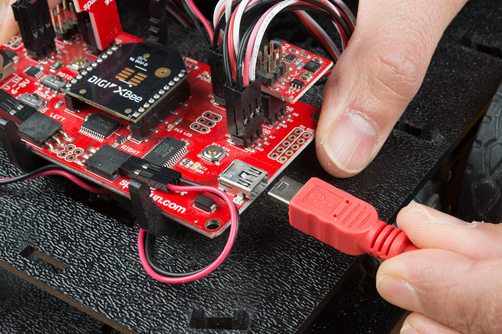
We'll assume that the buzzer is attached to pin 9 like the assembly guide. If you have not already, insert the XBee into the RedBot. Then connect the Redbot to your computer via USB cable.
Open the Sketch
Copy and paste the following code into the Arduino IDE.
language:c
/* 4_2_Full_Remote_Control_SAMD_Audio.ino
   Full Robot Control ATmega328P Example with Buzzer
   Written by: Ho Yun Bobby Chan
   Date: 2/15/19
   SparkFun Electronics

   license: Creative Commons Attribution-ShareAlike 4.0 (CC BY-SA 4.0)
   Do whatever you'd like with this code, use it for any purpose.
   Please attribute and keep this license.

   The first step to controlling the RedBot remotely is to first drive it
   from the Serial Monitor in a tethered setup. This is example code
   for the RedBot Mainboard with ATmega328P. After uploading this sketch,
   keep the RedBot tethered to your computer with the USB cable. Flip the
   switches to the respective sides: MOTOR => RUN and POWER => ON. You
   will also need to have UART flipped to the XBee_SW_Serial side.

   Assuming that you have a pair of XBees 1s (or 3 configured with
   802.15.4 protocol) on the same channel, a character will be
   transmitted wirelessly between the XBees. Any charactered received
   from the XBee connected to the software serial defined pins will
   be passed to the Serial Monitor. For troubleshooting, any character
   sent through the Serial Monitor will be echoed back. Try testing the
   controller to see if the robot will move forward or sending the following
   character through the Serial Monitor.

       A = forward
       B = forward turn right
       C = reverse
       D = forward turn left
       J = coast
       K = stop
       X = coin cointer sound effect
       Y = fireball sound effect

  If your motors are not moving forward when you send the forward command,
  simply flip the wiring. You can adjust the code but that would require
  adjusting more than one line of code. This does not account for motor
  intensity like the example that is used with the Wireless Joystick Example
  and RedBot Experiment 9.

  WARNING: Make sure to flip the switch to the XBEE_SW_SERIAL when
  you are uploading to the RedBot Mainboard. You will have issues uploading
  code and possibly brick your XBee.
*/

#include "pitches.h" //include pitches.h from tab

#include <RedBot.h>  //include RedBot library
RedBotMotors motors; //make instance of RedBot

char c_data;  // variable for holding incoming data from XBee to Arduino

// We'll use RedBot SoftwareSerial to communicate with the XBee:
// For Atmega328P's
// XBee's DOUT (TX) is connected to pin 14 (Arduino's Software RX)
// XBee's DIN (RX) is connected to pin 15 (Arduino's Software TX)
#include <RedBotSoftwareSerial.h>
RedBotSoftwareSerial RedBotXBee; //make instance of Software Serial, pins     defined already in modified Software Serial Library

//LED to check if the LED is initialized.
const int status_LED = 13;
int coin_counter = 0;//counter for coins and 1-up

void setup() {
  // Set up both ports at 9600 baud. This value is most important
  // for the XBee. Make sure the baud rate matches the config
  // setting of your XBee.
  RedBotXBee.begin(9600);// Initialize SW for XBee for receiving serial
  Serial.begin(9600);// Initialize HW for Serial Monitor for DEBUGGING

  //Status LED to see if the RedBot is initializing
  pinMode(status_LED, OUTPUT);
  for (int i = 0; i < 3; i++) {
    digitalWrite(status_LED, HIGH);//set Status LED on
    delay(50);
    digitalWrite(status_LED, LOW); //set Status LED off
    delay(50);
  }

  pinMode(9, OUTPUT); //buzzer

  tone(9, NOTE_E6, 125);
  delay(130);
  noTone(9);

  Serial.println("RedBot Initialized!");
}//end setup

void loop() {

  if (RedBotXBee.available() || Serial.available()) {
    if (RedBotXBee.available()) {
      c_data = RedBotXBee.read();//store received value from XBee into variable
    }

    else if (Serial.available()) {
      c_data = Serial.read();//store received value from Serial Monitor into variable
    }

    Serial.println("Character Received, ");
    Serial.write(c_data);//send it out to serial monitor
    Serial.println();
    digitalWrite(status_LED, HIGH); //turn ON Status LED
    //delayMicroseconds(500);//add short delay for LED for feedback, this can be commented out if it is affecting performance

    if (c_data == 'A') {
      Serial.println("Drive Forward");
      RedBotXBee.write('A');
      digitalWrite(status_LED, HIGH); //turn ON Status LED

      motors.drive(255); //forward
    }
    else if (c_data == 'B') {
      Serial.println("Turn Right");
      RedBotXBee.write('B');
      digitalWrite(status_LED, HIGH); //turn ON Status LED

      motors.leftMotor(-200); // Turn on left motor power (motorPower = )
      motors.rightMotor(100); // Turn on right motor power (motorPower = )
    }
    else if (c_data == 'C') {
      Serial.println("Reverse");
      RedBotXBee.write('C');
      digitalWrite(status_LED, HIGH); //turn ON Status LED

      motors.drive(-255); //reverse
    }
    else if (c_data == 'D') {
      Serial.println("Turn Left");
      RedBotXBee.write('D');
      digitalWrite(status_LED, HIGH); //turn ON Status LED

      motors.leftMotor(-100); // Turn on left motor power (motorPower = )
      motors.rightMotor(200); // Turn on right motor power (motorPower = )
    }
    else if (c_data == 'J') {
      Serial.println("Coast");
      RedBotXBee.write('J');
      digitalWrite(status_LED, HIGH); //turn ON Status LED
      motors.coast();
    }
    else if (c_data == 'K') {
      Serial.println("Stop");
      RedBotXBee.write('K');
      digitalWrite(status_LED, HIGH); //turn ON Status LED
      motors.stop();
    }
    else if (c_data == 'X') {
      // Play coin sound
      Serial.println("Coin Sound");


      if (coin_counter < 100) {
        coin_counter = coin_counter + 1; //add 1 coin
        Serial.print("Coin Counter = ");
        Serial.println(coin_counter);
        RedBotXBee.write('X');

        digitalWrite(status_LED, HIGH);  // turn the LED on

        tone(9, NOTE_B5, 100);
        delay(50);
        tone(9, NOTE_E6, 850);
        delay(400);
        noTone(9);
      }
      else if (coin_counter <= 100) {
        coin_counter = 0;//set back coins to 0;

        Serial.print("100 Coins Received! 1-Up");
        Serial.print("Coin Counter reset to = ");
        Serial.println(coin_counter);
        RedBotXBee.write('X');
        digitalWrite(status_LED, HIGH); //turn ON Status LED


        tone(9, NOTE_E6, 125);
        delay(130);
        tone(9, NOTE_G6, 125);
        delay(130);
        tone(9, NOTE_E7, 125);
        delay(130);
        tone(9, NOTE_C7, 125);
        delay(130);
        tone(9, NOTE_D7, 125);
        delay(130);
        tone(9, NOTE_G7, 125);
        delay(125);
        noTone(9);
      }

    }
    else if (c_data == 'Y') {
      // Play coin sound
      Serial.println("Fireball Sound");
      RedBotXBee.write('Y');

      digitalWrite(status_LED, HIGH); //turn ON Status LED

      // Play Fireball sound
      tone(9, NOTE_G4, 35);
      delay(35);
      tone(9, NOTE_G5, 35);
      delay(35);
      tone(9, NOTE_G6, 35);
      delay(35);
      noTone(9);
    }
  }

  //delay(100); // short pause so we are not constantly receiving characters
  digitalWrite(status_LED, LOW); //turn OFF Status LED
}//end loop
Adding a Tabbed File
Along with the example, you will need to include the following pitches.h header file that was originally written by Brett Hagman. You may remember this file being named notes.h. To make the pitches.h file, either click on the arrow button just below the serial monitor icon and choose "New Tab", or use Ctrl+Shift+N shortcut. Name the file as pitches.h to help break up the example sketch.
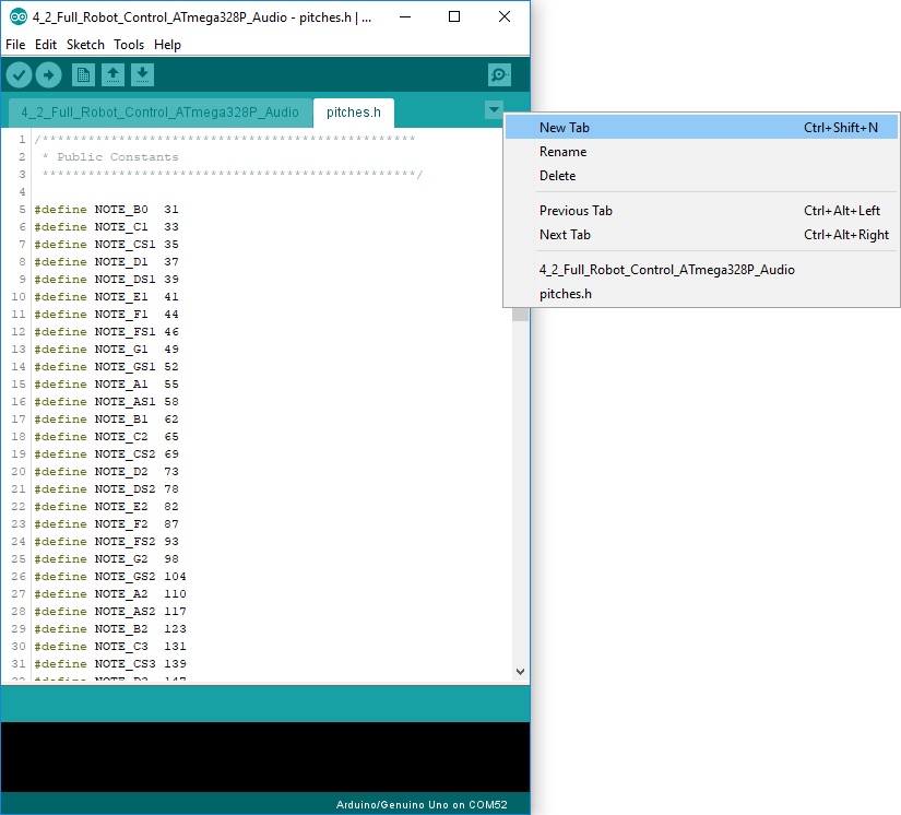
Copy and paste the following code the Arduino IDE's new tab and save. As a result, a new file will be included in the same folder as the example code. Remember, we will need to select Arduino/Genuino Uno for the RedBot mainboard, select the corresponding COM port that it enumerated on, and flip the POWER switch to the ON position. Once these settings are adjusted, you can hit the upload button.
language:c
/*************************************************
 * Public Constants
 *************************************************/

#define NOTE_B0  31
#define NOTE_C1  33
#define NOTE_CS1 35
#define NOTE_D1  37
#define NOTE_DS1 39
#define NOTE_E1  41
#define NOTE_F1  44
#define NOTE_FS1 46
#define NOTE_G1  49
#define NOTE_GS1 52
#define NOTE_A1  55
#define NOTE_AS1 58
#define NOTE_B1  62
#define NOTE_C2  65
#define NOTE_CS2 69
#define NOTE_D2  73
#define NOTE_DS2 78
#define NOTE_E2  82
#define NOTE_F2  87
#define NOTE_FS2 93
#define NOTE_G2  98
#define NOTE_GS2 104
#define NOTE_A2  110
#define NOTE_AS2 117
#define NOTE_B2  123
#define NOTE_C3  131
#define NOTE_CS3 139
#define NOTE_D3  147
#define NOTE_DS3 156
#define NOTE_E3  165
#define NOTE_F3  175
#define NOTE_FS3 185
#define NOTE_G3  196
#define NOTE_GS3 208
#define NOTE_A3  220
#define NOTE_AS3 233
#define NOTE_B3  247
#define NOTE_C4  262
#define NOTE_CS4 277
#define NOTE_D4  294
#define NOTE_DS4 311
#define NOTE_E4  330
#define NOTE_F4  349
#define NOTE_FS4 370
#define NOTE_G4  392
#define NOTE_GS4 415
#define NOTE_A4  440
#define NOTE_AS4 466
#define NOTE_B4  494
#define NOTE_C5  523
#define NOTE_CS5 554
#define NOTE_D5  587
#define NOTE_DS5 622
#define NOTE_E5  659
#define NOTE_F5  698
#define NOTE_FS5 740
#define NOTE_G5  784
#define NOTE_GS5 831
#define NOTE_A5  880
#define NOTE_AS5 932
#define NOTE_B5  988
#define NOTE_C6  1047
#define NOTE_CS6 1109
#define NOTE_D6  1175
#define NOTE_DS6 1245
#define NOTE_E6  1319
#define NOTE_F6  1397
#define NOTE_FS6 1480
#define NOTE_G6  1568
#define NOTE_GS6 1661
#define NOTE_A6  1760
#define NOTE_AS6 1865
#define NOTE_B6  1976
#define NOTE_C7  2093
#define NOTE_CS7 2217
#define NOTE_D7  2349
#define NOTE_DS7 2489
#define NOTE_E7  2637
#define NOTE_F7  2794
#define NOTE_FS7 2960
#define NOTE_G7  3136
#define NOTE_GS7 3322
#define NOTE_A7  3520
#define NOTE_AS7 3729
#define NOTE_B7  3951
#define NOTE_C8  4186
#define NOTE_CS8 4435
#define NOTE_D8  4699
#define NOTE_DS8 4978
Code to Note
We'll include the pitches.h file at the beginning of the example to reference the notes. Then we'll setup the buzzer and play a sound to ensure that the buzzer is working as expected. Further in the loop() function after our condition statements, we'll add a few lines to make the buzzer play a sequence of notes. If one of the triggers is pressed 100 times, we'll play a special sequence of notes.
What You Should See (and Hear)
Press the triggers on the controller. You should hear a familiar 8-bit sound effect from a popular game coming from the piezo buzzer! Press one of the triggers 100 times to hear yet another familiar sound!