Wireless Timing Project
Broncos Country, Let's Race!

The standard “Combine” assessment is the gold standard for evaluating athlete performance throughout the NFL. The 2022 NFL Draft combine had over 55 million viewers around the world and the 40-yard dash times were amongst the top discussions.
There are two techniques for timing the athlete's 40-yard dash; hand timing, and fully automated electronic timing. As you probably know, hand timing consists of manually starting and stopping time as the athlete crosses the start and finish line. Fully automated electronic timing methodologies are used to mitigate human error, whereby the actions of the athlete will start and stop the time. Typically, an athlete will have a “slower” 40-yard dash time if they are timed using a fully automated timing system. These electronic systems are extremely expensive costing the average Joe more than $600 for one setup. Inspired by the significance of the 40-yard dash and its costly market, we set out to replicate this timing system using only SparkFun components.
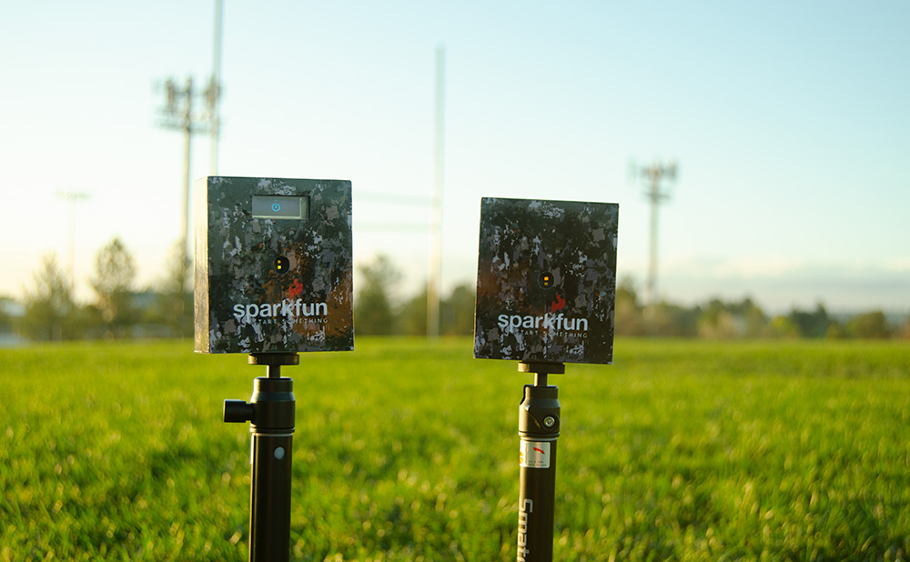
The components used in this tutorial were miles less expensive than the average timing system in today's market. This system brought great ideas for mild horseplay in the workplace, but of course, safety first, not third. We decided to host a company 40-yard dash competition, winner took home bragging rights and a visa gift card.
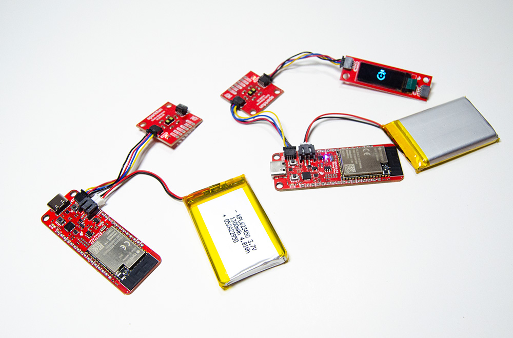
In this tutorial, you will learn how to create a wireless timing system using the ESP32 WIFI system. This system can be used in limitless applications involving timing such as running, driving, dog racing, robot racing, etc. The hardware includes a pair of ESP32-S2 Thing Plus, two SparkFun Distance Sensor Breakouts 4 Meter VL53L1X, two Metal Pushbuttons, a SparkFun Qwiic Cable Kit, a SparkFun qwiic OLED display, and two Lithium Ion Batteries. You can add all components to your cart using the wish list below:
Required Materials
To follow along with this tutorial, you'll need the following materials.
ESP32 MAC Address

We will be setting up the ESP32 devices as access points. This will give the ESP32’s the ability to create their own WIFI network, which provides communication between the two devices. In order to receive two-way communication, we need to know the Media Access Control (MAC) address of one ESP32 device. There is a great tutorial, Sending Sensor Data Over Wifi, made by our very own Rob Reynolds, which goes into depth on discovering the MAC address of an ESP32. Take a look at this tutorial and follow the instructions for Step 1: Obtaining Mac Address. We are sending a trigger from the start ESP32 to the finish ESP32, you will only need to obtain the mac address for the ESP32 that you plan to use at the finish line. Here is the code Rob has created for us to find the MAC address:
/*
 * MAC Address Finder
 * Run this on each of your WiFi-enabled
 * boards to get their MAC addresses, so
 * you can plug them into your code,
 * allowing your components to connect
 * on power-up or after power-cycling
 * without the need for any intervention!
 *
 * Once you've uploaded the code, open
 * the Serial Monitor, hit the reset
 * button on your board, and write down
 * the MAC address.
 * (I use a label maker to put the MAC
 * address on the back of each board.)
 */

#include "WiFi.h"

void setup(){
  Serial.begin(115200);

}

void loop(){
  WiFi.mode(WIFI_STA);
  Serial.print("The MAC address for this board is: ");
  Serial.println(WiFi.macAddress());
  while(1){     // This holds the loop, so it doesn't
    }           // print the info a million times.
}
Connecting the Hardware
The qwiic connect ecosystem has made this project practically solderless, although we are going a little over the top and adding a metal pushbutton that requires soldering. It’s best to split the start and finish into two separate setups, then finish up by adding the casing and pushbuttons.
If you aren't familiar with the Qwiic system or new to SparkFun electronics, we recommend utilizing these tutorials. Our tutorials will go in depth on the basics of setting up your devices. Also, nothing goes as expected when creating a project, so these will be great resources for troubleshooting.
 |
| Qwiic Connect System |
How to Solder: Through-Hole Soldering
Serial Communication
Serial Peripheral Interface (SPI)
Installing Arduino IDE
Analog vs. Digital
How to Work with Jumper Pads and PCB Traces
ESP32 Thing Plus Hookup Guide
How to Install CH340 Drivers
Installing Board Definitions in the Arduino IDE
Start Setup
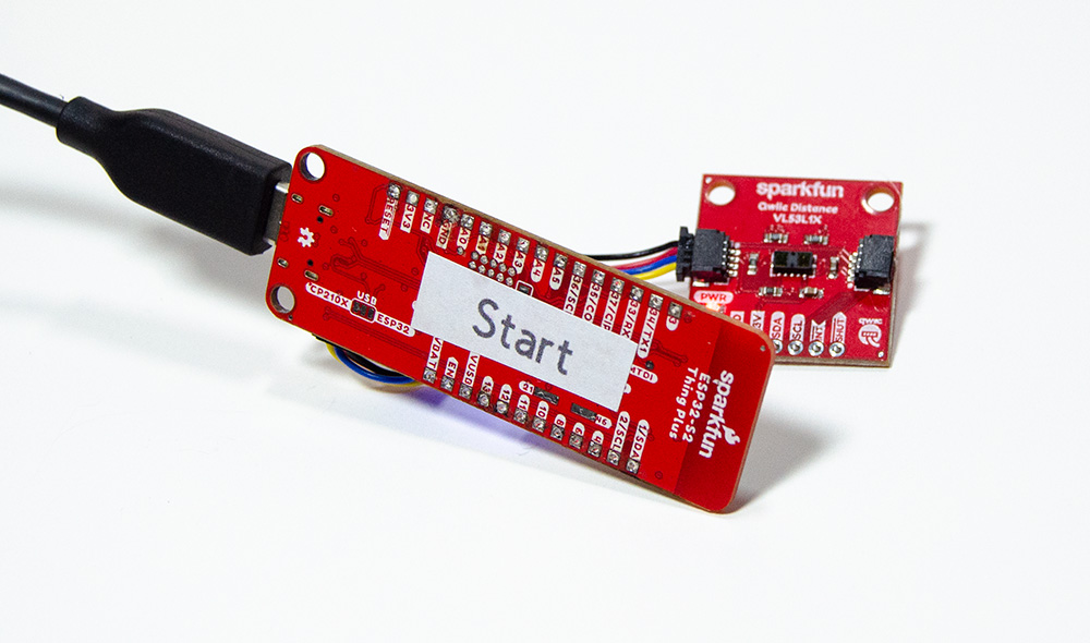
For the start setup, we will need to connect the distance sensor to the ESP32 Thing Plus. This is the “Start”, so be sure this is the ESP32 that we did NOT obtain the MAC address for. Use one qwiic cable connecting the ESP32 to our distance sensor. Your setup should look like this.
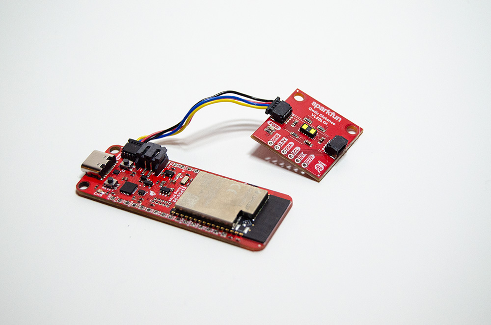
Once we have connected the distance sensor, we are now ready to flash the ESP32 with our “Start” code.
This code controls sending a message to our “Finish” ESP32 when the distance sensor has been triggered. The distance sensor will continuously scan at 4m. When an object crosses the sensor, the distance will be less than 1500mm. Why 1500mm? It’s what the sensor was reading when there was no object interfering. If the sensor is triggered or distance is less than 1500mm, we will send an integer “1” to the “Finish” ESP32. The “Finish” ESP32 is always looking out for the “1”. When the “1” integer is received, the “Finish” device will begin the time and wait for another distance sensor trigger. This will be the time the object is between the start and finish lines.
/*
*Wireless timing start sensor example, Transmitter sketch
*Giordan Thompson, SparkFun Electronics, September 2022
*This example transmits data to the finish sensor example
*You can find this example in github here ()
*
*The purpose of this code is to provide functionality to our wireless timing system
*This code will send data to the finish sensor, relaying the start sensor has been triggered
*and we are ready to begin the timing.
*
*Complete project details can be found here () where we dive into the creation and
*desciption of this system.
*Please feel free to customize this code to your needs and raise an issue if necessary.
*
*Enjoy!!!
*
*/


#include <Wire.h> //used to establish serial communication on the I2C bus
#include "SparkFun_VL53L1X.h" //Distance sensor library
#include <esp_now.h> //ESP wireless communication library
#include <WiFi.h>

SFEVL53L1X distanceSensor;

// REPLACE WITH YOUR RECEIVER MAC Address
uint8_t broadcastAddress[] = {0x7C, 0xDF, 0xA1, 0x55, 0xAE, 0x50};

// Structure example to send data
// Make sure to match the receiver structure on finish sensor
typedef struct struct_message {
 int outgoingInt;
} struct_message;

// Create a struct_message called myData
struct_message myData;

// callback when data is sent
void OnDataSent(const uint8_t *mac_addr, esp_now_send_status_t status) {
 Serial.print("\r\nLast Packet Send Status:\t");
 Serial.println(status == ESP_NOW_SEND_SUCCESS ? "Delivery Success" : "Delivery Fail");
}

void setup() {
//Pin for indecator LED
 pinMode(13, OUTPUT);

 Wire.begin();

 Serial.begin(115200);

  // Device ia set as a Wi-Fi Station
  WiFi.mode(WIFI_STA);

  // Init ESP-NOW
  if (esp_now_init() != ESP_OK) {
    Serial.println("Error initializing ESP-NOW");
    return;
  }

  // Once ESPNow is successfully Init, we will register for Send CB to
  // get the status of Trasnmitted packet
  esp_now_register_send_cb(OnDataSent);

  // Register peer
  esp_now_peer_info_t peerInfo;
  memcpy(peerInfo.peer_addr, broadcastAddress, 6);
  peerInfo.channel = 0;
  peerInfo.encrypt = false;

  // Add peer otherwise indecate failure
  if (esp_now_add_peer(&peerInfo) != ESP_OK){
    Serial.println("Failed to add peer");
    return;
  }


  //Communicate sensor is online and ready for trigger
  if (distanceSensor.init() == false)
    Serial.println("Sensor online!");

}

void loop() {
  //Indicator light on, device is ready for trigger
  digitalWrite(13, HIGH);

  distanceSensor.startRanging(); //Write configuration bytes to initiate measurement
  int distance = distanceSensor.getDistance(); //Get the result of the measurement from the sensor
  //Serial.print(distance);
  //After testing, 1500 was a consitent sensor value with NO object interference
  if (distance < 1500){

    //Sensor has been tiggered, send "1" integer to finish sensor
    myData.outgoingInt = 1;

    //Serial communication for troubleshooting
    Serial.print("Outgoing Int Val:");
    Serial.println(myData.outgoingInt);
    esp_err_t result = esp_now_send(broadcastAddress, (uint8_t *) &myData.outgoingInt,sizeof(myData.outgoingInt));
    Serial.println("Distance(mm): ");
    Serial.print(distance);

    //Sensor tiggered and integer has been sent to finish ESP
    //now ready to pause code and wait for reset
    distanceSensor.stopRanging();
    digitalWrite(13, LOW);
    while(1);
  }

  delay(10);

}
Finish Setup
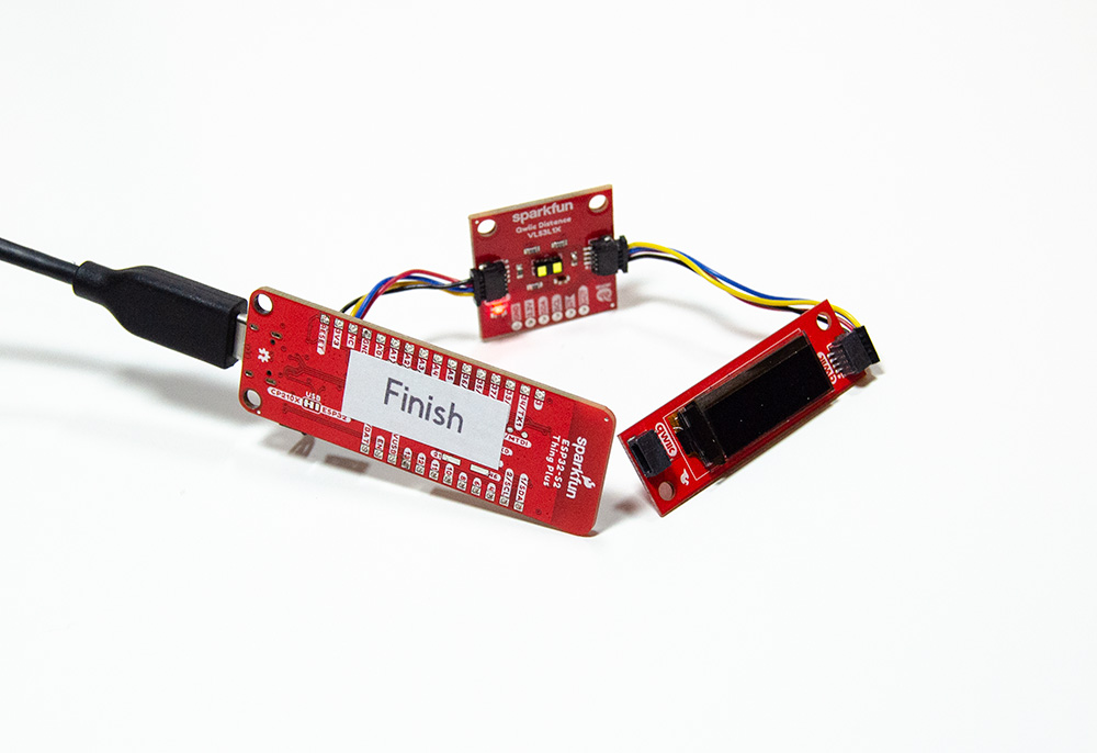
The “Finish” setup is a little bit more involved than the “Start” setup. For the “Finish”, we have an ESP32, distance sensor, Metal Pushbutton, and display. To make all these components work in harmony, we will need considerably more code than the “Start”. We will begin by connecting the sensor and OLED display to the ESP32 via qwiic connect.
When your hardware is all set, we can move to flashing the device with our “Finish” code. The “Finish” code will run through its setup, getting the distance sensor up and running. When the “Start” ESP32 has been triggered, this code will receive a “1” integer and jump into the VOID loop “if” function. This function will set the distance sensor to begin taking measurements and wait for an object to trigger a measurement less than 1500mm. Meanwhile, the display will begin displaying the elapsed time of the race. When the sensor is triggered, the display will stop and the Void Loop will reach a “while(1)”. The purpose of the “while(1)” is to pause the code from going any further in the void loop. When the code is paused, the display will show the total elapsed time in seconds. This is where the reset pushbutton comes in handy, because the next step is to record your time on a piece of paper and restart the setup for the next race.
/*
*Wireless timing Finish Sensor example, Reciever sketch
*Giordan Thompson, SparkFun Electronics, September 2022
*This example is recieves data from the Start Sensor example
*You can find the Start Sensor example in github here ()
*
*The purpose of this code is to provide functionality to our wireless timing system
*This code will recieve data from the Start Sensor, Start and Stop time as the sensor is
*triggered during our race.
*
*Complete project details can be found here () where we dive into the creation and discription
*of this system.
*Please feel free to customize this code fit your needs and as always please feel free to
*raise an issue
*
*Enjoy!!
*
*/


#include <esp_now.h> //ESP wireless communication library
#include <Wire.h> //Used to establish serial communication on the I2C bus
#include <WiFi.h>
#include "SparkFun_VL53L1X.h" //Distance Sensor Library
//#include <Adafruit_GFX.h> //Font Library
#include <Adafruit_SSD1306.h> //OLED Display Library
#include <Fonts/FreeSans9pt7b.h> //special font Library

#define SCREEN_WIDTH 128 // OLED display width, in pixels
#define SCREEN_HEIGHT 32 //OLED display hieght, in pixels
#define OLED_RESET -1  // GPIO -1
#define SCREEN_ADDRESS 0x3C //OLED diplay address

Adafruit_SSD1306 display(SCREEN_WIDTH, SCREEN_HEIGHT, &Wire, OLED_RESET);

SFEVL53L1X distanceSensor2;

//define variables used in this example
int start=0;
int min1=0;
unsigned long tim=0;
unsigned long msec=0;
unsigned long mili=0;
int sec1=0;

//OLED display logo
const unsigned char PROGMEM icon [] = {
0x00, 0x1F, 0xF8, 0x00, 0x00, 0x1F, 0xF8, 0x00, 0x00, 0x1F, 0xF8, 0x00, 0x00, 0x1F, 0xF8, 0x00,0x00, 0x1F, 0xF8, 0x00, 0x00, 0x03, 0xC0, 0x00, 0x00, 0x00, 0x00, 0x40, 0x00, 0x00, 0x00, 0xE0,0x00, 0x1F, 0xF8, 0xF0, 0x00, 0x7F, 0xFE, 0x70, 0x00, 0xFF, 0xFF, 0x20, 0x01, 0xF0, 0x0F, 0x80,0x03, 0xC1, 0x83, 0xC0, 0x03, 0x81, 0x81, 0xC0, 0x07, 0x01, 0x80, 0xE0, 0x07, 0x01, 0x80, 0xE0,0x0E, 0x01, 0x80, 0x70, 0x0E, 0x01, 0x80, 0x70, 0x0E, 0x03, 0xC0, 0x70, 0x0E, 0x03, 0xC0, 0x70,0x0E, 0x03, 0xC0, 0x70, 0x0E, 0x01, 0x80, 0x70, 0x0E, 0x00, 0x00, 0x70, 0x07, 0x00, 0x00, 0xE0,0x07, 0x00, 0x00, 0xE0, 0x07, 0x80, 0x01, 0xE0, 0x03, 0xC0, 0x03, 0xC0, 0x01, 0xE0, 0x07, 0x80,0x00, 0xF8, 0x1F, 0x00, 0x00, 0x7F, 0xFE, 0x00, 0x00, 0x1F, 0xF8, 0x00, 0x00, 0x07, 0xE0, 0x00


};

//Structure example to send data
//Make sure to match the transmitter structure of Start Sensor "a" used for simplicity
typedef struct struct_message {
    int a;

} struct_message;

//Create a struct_message called incomingReading
struct_message incomingReading;

//Callback when data is recieved
void OnDataRecv(const uint8_t * mac, const uint8_t *incomingData, int len) {
  memcpy(&incomingReading, incomingData, sizeof(incomingReading));

  Serial.print("Incoming Reading Val:");
  Serial.print(incomingReading.a);
}


void setup() {
  Serial.begin(115200);

  //Pin for indecator LED
  pinMode(13, OUTPUT);

  Wire.begin();

  // Set device as a Wi-Fi Station
  WiFi.mode(WIFI_STA);

  // Init ESP-NOW
  if (esp_now_init() != ESP_OK) {
    Serial.println("Error initializing ESP-NOW");
    return;
  }

  // Once ESPNow is successfully Init, we will register for recv CB to
  // get recv packer info
  esp_now_register_recv_cb(OnDataRecv);

  //Communicate sensor is online and ready for trigger
  if (distanceSensor2.init() == false)
    Serial.println("Sensor2 online!");

  //Display Setup
  display.begin(SSD1306_SWITCHCAPVCC, SCREEN_ADDRESS);
  display.display();
  display.clearDisplay();
  display.setCursor(50,0);
  display.print("Start");
  display.drawBitmap(48, 0,  icon, 32, 32, WHITE);
  display.display();
  delay(2000);

}


void loop() {

  //indicator light on, device is ready for trigger
  digitalWrite(13, HIGH);

  //Begin time when integer "1" has been recieved from the Start Sensor
  //Object has crossed Start Sensor when message recieved
  if (incomingReading.a == 1)
  {
    display.clearDisplay();
   distanceSensor2.startRanging();

    display.setTextSize(2);
    display.setTextColor(SSD1306_WHITE);

    if(start==0)
          {
           start=1;
           tim=millis();
         }
      msec=(millis()-tim);


       min1=msec/60000;


        if((msec/1000)>59)
           {
            sec1=(msec/1000)-(min1*60);
           }else{
             sec1=msec/1000;
             }

         mili=(msec%1000)/10;

          display.setCursor(0,30);
          //if(min1<=9)
         //{

         // }

            if(sec1<=9)
          {
           display.print("0");
           display.print(sec1);
           }else {display.print(sec1);}
           display.print(".");
           display.setFont(&FreeSans9pt7b);

            if(mili<=9)
          {
           display.print("0");
           display.print(mili);
           }else {display.print(mili);
           display.setTextSize(1);
                   display.print("sec");}


   int distance = distanceSensor2.getDistance();

   //After testing, 1500 was a consistent sensor value with NO object interference
    //pause code when the sensor has been triggered
    if (distance < 1500){
     Serial.print("Distance: ");
     Serial.print(distance);
     distanceSensor2.stopRanging();
     Serial.print("Sensor 2 Stop Ranging...");
      digitalWrite(13, LOW);
      while(1);
    }
  }

  display.display();

}
Test
Now that we have the hardware and code ready for both setups, we should test that our devices work properly. To do this, find an area to place your sensors, with no objects within 4m. This will help make sure we have no interference with your distance sensors. Set this up similarly to a race, with “Start” and “Finish” in sequential order. Make sure both devices are reset and ready for an object to trigger the sensors. An easy quality control (QC) test, is to wave your hand over the “Start”, wait a moment, then wave your hand over the “Finish” sensor.
To know your devices are functioning, the elapsed time will be displayed on the OLED display. How did you do? If you are having trouble, please refer to the attached tutorials, where you can get some ideas for finding a solution.

3D Printing
If your setup passed QC, congratulations, and welcome to the case section. There are lots of free CAD software on the internet like tinker CAD, Onshape, and SketchUp. We challenge you to design a better case! If you're not up for the challenge, no big deal, it can be a ton of work.
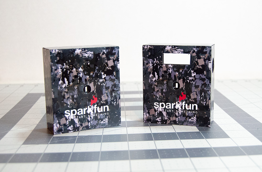
This tutorial uses Onshape to design the case, which is an open-source software that allows you to share designs with the public. Click the link and you will find all the files you need to 3D print the case. It takes a little trial and error to find the optimal printer settings for this print. For those curious, we used a fine layer height, 20% infill, extrusion temperature of 200°C, and a bed temperature of 55°C. The case print for both the “Start Case” and “Finish Case” take 6hrs to print. The “Lid” takes roughly 1.5 hrs, so in total, we are looking at around 15hrs of print time.
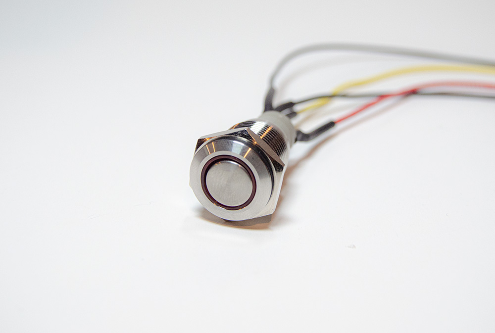
Metal Indicator Pushbutton
We saved this step for last because you will need to size your hookup wire to fit within your casing. For this step, we used some hookup wire, lead-free solder, a soldering iron, heat shrink, and a heat gun. For those looking to get their hands on this equipment, check out the list below.
To get started, we recommend soldering your hookup wire to the headers on the pushbuttons. Our very talented BBOYHO has created this incredible table to show us the solder points on the momentary pushbutton.
| Component | Component Pin | ESP32 I/O Pin |
|---|---|---|
| Red Momentary Metal Pushbutton | + : LED Anode Side | 13 |
| NC1: Normally Closed Pin | ||
| NO1: Normally Open Pin | RESET | |
| C1: Common Pin | GND | |
| -: LED Cathode Side | GND |
It’s best to do all soldering in one sitting to mitigate going back and forth between setups. Please be sure that your wire is long enough to reach the button within your casing. Our setup had roughly 5 inch cuts for each wire. Once you have soldered the button leads, place some heat shrink on the leads and secure them using your heat gun.
Now, we are ready to place the buttons inside our casing.
Assembly
Now that we have the case and buttons soldered, it is time to assemble the two “Start” and “Finish” devices. For this, you will need a hot glue gun and of course some hot glue. A hot glue gun is your best friend for prototyping any components that need secure positions, so if you don't have one we recommend getting one.
First, let us begin with the “Start” case. Insert and fasten the pushbutton to the wall of your case. Then soldered the metal push button leads to pins 13, GND, and RESET. Once this is complete, grab your battery and plug it into the ESP32. Again, make sure this is the ESP32 that you do not have the MAC address for. Next, we will need to secure all the components in our case to ensure there are no moving parts when the device is in use. The order of gluing these parts to the case is up to you, but make sure you do not cover the sensor lens. Finish up by connecting the distance sensor to the ESP32 via qwiic.
Now let us finish up with assembling the “Finish” setup. Insert and fasten the pushbutton to the wall of your case. Then soldered the metal push button leads to pins 13, GND, and RESET. Grab your battery and plug it into the ESP32. Make sure this is your “Finish” ESP-32 with MAC address. Glue the distance sensor and OLED display to your case. Qwiic tip, be very careful when gluing the OLED display, the device is fragile and took us a couple attempts. Finish up by connection the distance sensor to the ESP32 via qwiic. Your final setup should look similar to the image below.

Instructions
Now that we have completed our build, its time for action! The devices are simple to use, but can be finicky at times. Place your "Start" sensor at the starting line and you "Finish" sensor at the finish. Press the reset button on the "Start" sensor and make sure the red LED halo is on. This verifies the sensor is ready to be triggered. Now, complete the same for the "Finish" sensor. Once both reset buttons are illuminating, we are ready to begin our race. Ready, set, go!
Resources and Going Further
The purpose of this tutorial was to create a comparatively inexpensive product to the wireless timing systems on the market. If you'd like to go further, there are many components you can swap out for your needs. Maybe a better display or distance sensor... Or maybe you'd like to add a camera for photo finishes. We've added some great resources to help you get started. Spark Fan's, let us know how your next wireless timing project goes. What's different from ours?