XBee Shield Hookup Guide
 jimblom
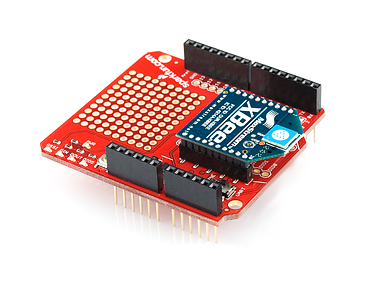
Hardware Overview
Here's a quick overview of the most components of the XBee Shield:
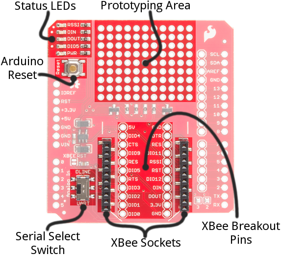
Below we'll go more in-depth on the most important components of the shield.
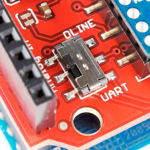
UART/Software Serial Switch
One of the most important components on the XBee Shield is the DLINE/UART switch. This switch controls which Arduino pins interface with the XBee.
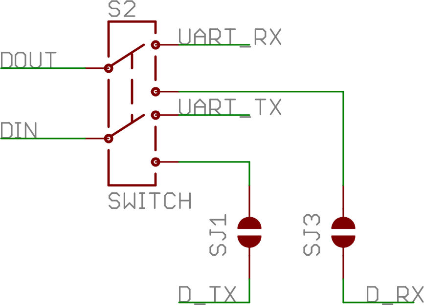
The Arduino Uno has a single hardware UART, which is usually either used for programming (via the Arduino's serial bootloader) or communication with the serial monitor. That serial port can only be used to communicate with one device at any time, lest you run into problems of bus contention. There's also a chance that, during program upload, spurious -- even harmful -- data might be sent to any device attached to the Arduino's hardware UART.
So to avoid any problems that might arise from connecting the XBee to the Arduino's hardware UART, we usually take advantage of the Software Serial library, connecting the XBee's RX and TX pins to a pair of free digital pins on the Arduino.
To select between software and hardware serial, the XBee Shield includes a small, surface-mount slide switch. This switch allows you to select between the hardware serial port (UART position) and a software serial port connected to pins 2 (Arduino-side RX) and 3 (Arduino-side TX).
For all of our example sketches we'll assume the switch is in the DLINE position. At the very least, make sure the switch is in the "DLINE" position when uploading sketches.
Status LED Indicators
There are 5 LEDs on the XBee Shield. Each of these LEDs connects to a pin on the XBee, which does most of the LED driving. Here's a table explaining the operation of each LED:
| LED Label | LED Color | XBee Pin Connection | Default Operation Notes |
|---|---|---|---|
| PWR | Red | 3.3V | Indicates power is present. |
| DIO5 | Green | Associate/DIO5 | Associated indicator -- blinks when the XBee is associated with another XBee. |
| DOUT | Red | DOUT | Indicates wireless data is being received. |
| DIN | Green | DIN | Indicates wireless data is being transmitted. |
| RSSI | Green | PWM0/RSSI | Indicates relative signal strength (RSSI) of last received transmission. |
These LEDs can be very useful for debugging. The DIO5/Associate indicator should blink when the XBee is paired with a compatible device. The RSSI LED is actually PWM'd so it will be brighter when the paired XBee is closer (sending a stronger signal).
Assembly Tips
Before you can use the XBee Shield with your Arduino, you'll need to solder in some headers.
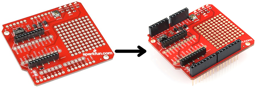
Check out the assembly page of our Shield tutorial for all of the tips and tricks related to header installation.
XBee Socket
There is some white silkscreen on the Shield PCB to help orient your XBee as you're plugging it in. Make sure to match up the XBee's two diagonal edges with the two diagonal lines on the PCB.
With everything installed, you're ready for the next step! Time to code...