What is MicroMod?
MicroMod is a solderless, modular interface ecosystem that uses the M.2 standard to mix and match your choice of processor with specific Function Boards or stand-alone Carrier Boards.
Either use Function Boards on a Main Board...
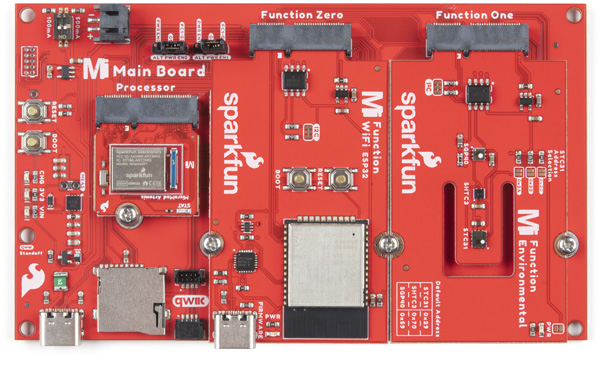
Match a Function Board (or two) with a Processor Board of your choice to a Main Board for a custom solution with consistent footprints.
See available Main and Function Boards
...or use Carrier Boards
Choose from 8 different Carrier Boards to access specific inputs and outputs based on your specific needs and pair with a Processor Board of your choice.
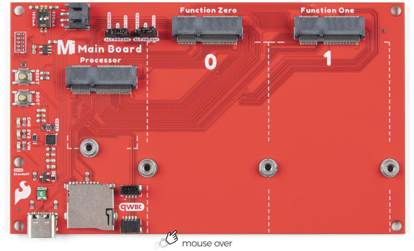
Main Boards and Function Boards
MicroMod Main Boards are specialized carrier boards that allow you to interface a MicroMod Processor Board alongside one or two Function Boards. Function Boards add a certain functionality to a Main Board.
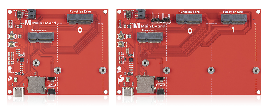
MicroMod Main Boards
Main Boards (above) are the home for Function Boards and Processor boards (below) to be plugged into the onboard M.2 connectors.
Key features:
Connectors alinged to a single side
Onboard LiPo charger
Micro-SD card slot for data logging
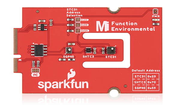
Environmental Function Board
Add environmental sensing to youer main board.
Key features:
Air quality sensor (SGP40)
Humidity & Temperature (SHTC3)
CO2 concentrations (STC31)
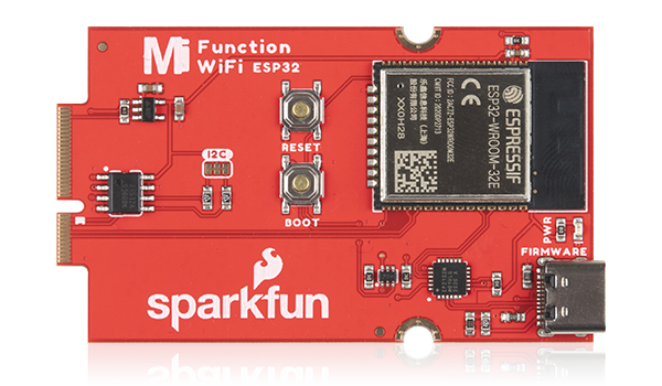
WiFi Function Board - ESP32
Add additional WiFi and/or Bluetooth options to your main board.
Key features:
16MB of flash memory with 520kB of internal SRAM
Integrated 802.11 b/g/n WiFi transceiver
Dual-mode Bluetooth capabilities
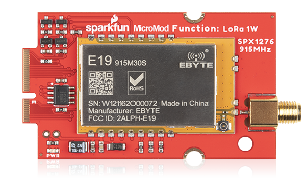
LoRa Function Board
Provide LoRA and LoRaWAN capabilities to your MicroMod project.
Key features:
RP-SMA connector for 915MHz antennas
Configurable U.FL antenna connector
37.5kbps (max) data rate
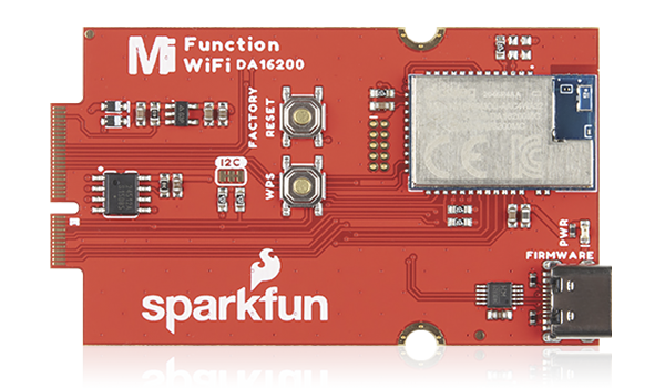
WiFi Function Board - DA16200
Fully integrated WiFi module from Arm and Dialog
Key features:
On-board chip antenna
32.7KHz Real Time Clock
4MB flash memory
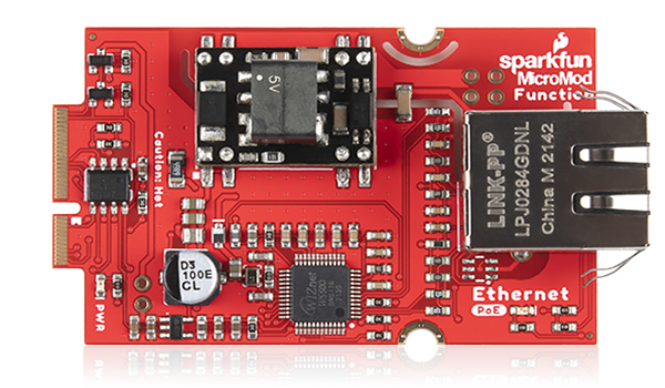
Ethernet Function Board
Integrate an Ethernet network including Power-over-Ethernet
Key features:
WIZnet W5500 Ethernet Controller
Ag9900M PoE DC/DC converter
RJ45 Connector with 10/100 Base-T Integrated Magnetics for PoE Applications
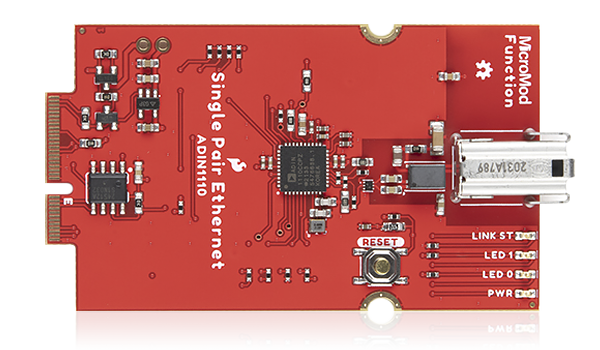
Single Pair Ethernet Function Board
Introduce 10BASE-T1L Two-Wire Ethernet protocol to your MicroMod project.
Key features:
Speeds up to 10Mbps
1km transmission distance
10BASE-T1L IEEE Standard 802.3cg-2019
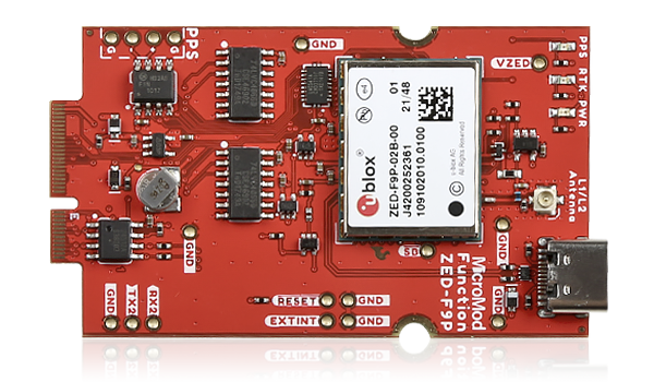
GNSS Function Board - ZED-F9P
High accuracy GNSS-RTK location board capable of millimeter-level, three dimensional accuracy.
Key features:
0.010m Horizontal Position Accuracy with RTK
Receives both L1C/A and L2C bands
Concurrent reception of most GNSS constellations
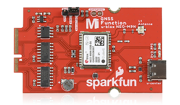
GNSS Function Board - NEO-M9N
A GNSS board featuring the u-blox NEO-M9N module with good positional accuracy and lock time.
Key features:
1.5m Horizontal Position Accuracy
25Hz Max Update Rate (four concurrent GNSS)
GPS, GLONASS, Galileo and BeiDou
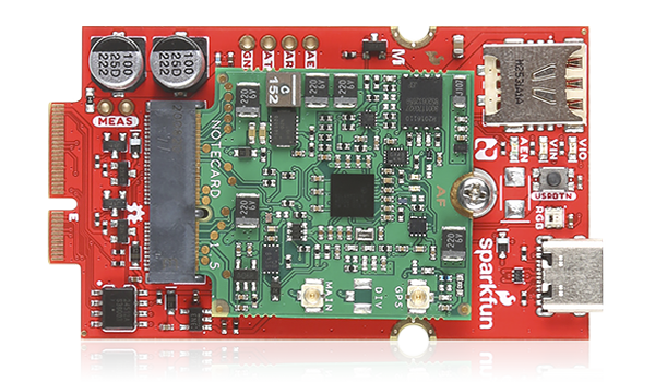
Blues Wireless Function Board
Use this cellular solution with that comes with a 10-year subscription and 500mb of data.
Key features:
Built-in SIM card
Subscription includes 500MB of data
Onboard GPS, 3-axis accelerometer & temp sensor
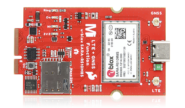
LTE GNSS Function Board - SARA-R5
Combine the power and connectivity of location and 5G-ready cellular data all on a single package.
Key features:
Asset tracking abilities via LTE and GNSS
Secure Cloud LTE-M communication for multi-regional use
Supports TCP/IP, FTP, HTTP (Get/Put/Post) and SMS
Carrier Boards
Carrier boards are focused on specific capabilities by providing access to focused peripherals and functionality.
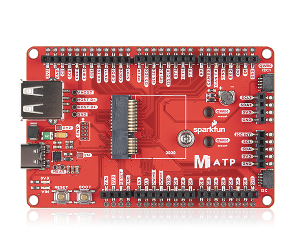
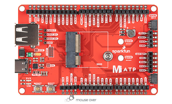
ATP
Access all the pins on your processor board.
Key features:
M/F connections for each pin
Mounting points for Qwiic boards
USB-A for host support
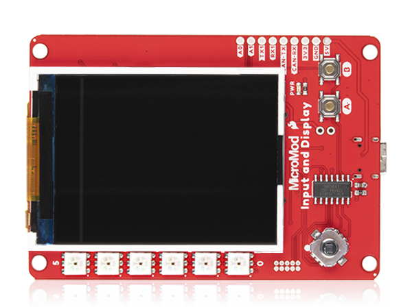
Input and Display
A great way to add data and input visibility.
Key features:
2.4" TFT Display
6 addressable LEDs
6 pin IO connector
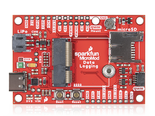
Data Logging
A customizable, low-power data logger.
Key features:
LiPo charging circuit
Power control of Qwiic and add-on peripherals
I2C, SPI, UART interface
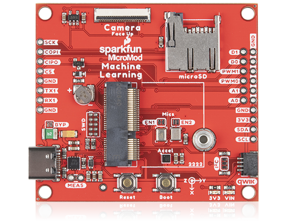
Machine Learning
Explore ML without a central computer or web connection.
Key features:
2 MEMS microphones
3-axis accelerometer
Himax camera connector
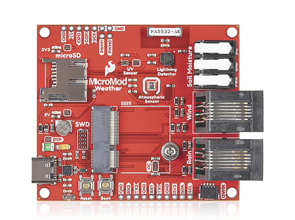
Weather
Create a weather station with your choice of processor.
Key features:
3 onboard sensors
RJ11 jacks (wind & rain)
Soil moisture terminals
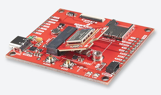
Asset Tracker
A toolkit to monitor and track the location of your assets.
Key features:
u-blox SARA-R510M8S for datacom
u-blox M8 receiver for positioning
“Wake On Motion” IMU support
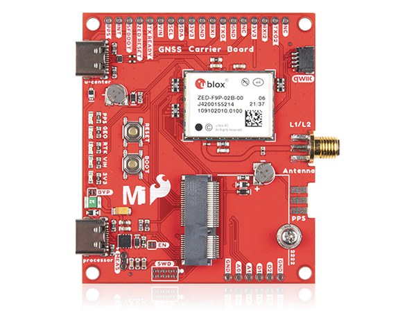
GNSS
High accuracy GNSS location solutions capable of 10mm, three-dimensional accuracy.
Key features:
GPS, GLONASS, Galileo and BeiDou
Receives both L1C/A and L2C bands
1cm Horizontal Position Accuracy with RTK
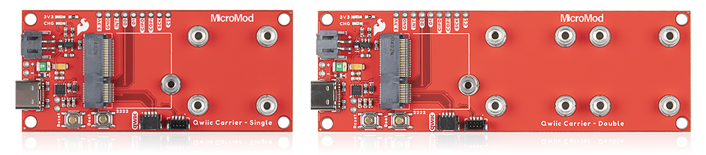
Qwiic Carrier Boards
Rapid prototype with your choice of Qwiic devices.
Key features:
Horizontal and vertical Qwiic connectors
4-40 screw inserts
On-board charge circuit
Processor Boards
Choose from a seriously impressive list of Processor Boards to power either your Main Board or a Carrier Board.
Artemis Processor Board
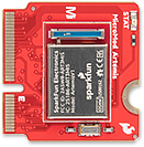
Choose the ultra-efficient ARM Cortex-M4F with BLE 5.0 running up to 96MHz and power as low as 6uA/MHz (less than 5mW).
| Processor | Clock Speed | Flash | RAM | Other Features |
|---|---|---|---|---|
| ARM Cortex-M4F | 48MHz (96 capable) | 1MB | 384kB | TensorFlow Lite Capable |
Teensy Processor Board
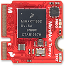
Yep, you read that right, Teensy from PJRC! Leverage the awesome computing power of the NXP iMXRT1062 chip.
| Processor | Clock Speed | Flash | RAM | Other Features |
|---|---|---|---|---|
| ARM Cortex-M7 | 600MHz | 16MB | 1024kB | Customizable pins |
Teensy Processor Board with Copy Protection
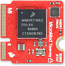
All the great performace of the aformentioned Teensy Processor Board with added copy protection which encrypts your program while compiling.
| Processor | Clock Speed | Flash | RAM | Other Features |
|---|---|---|---|---|
| ARM Cortex-M7 | 600MHz | 16MB | 1024kB | Customizable pins |
ESP32 Processor Board
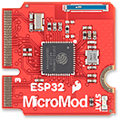
Plug in Espressif's power-packed processor board with the dual-core Tensilica LX6, with integrated Bluetooth and WiFi.
| Processor | Clock Speed | Flash | RAM | Other Features |
|---|---|---|---|---|
| Dual-core Tensilica LX6 | 240MHz | 128Mb/16MB (external) flash | 520kB SRAM | WiFi and dual-mode Bluetooth |
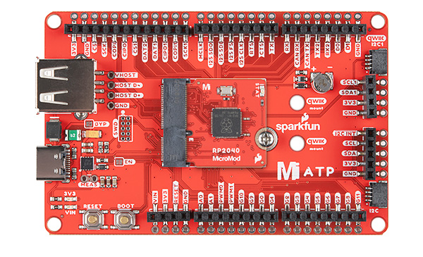
RP2040 Processor Board
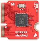
Slide in the first ever microcontroller chip straight from Raspberry Pi! The RP2040 boasts very detailed documentation.
| Processor | Clock Speed | Flash | RAM | Other Features |
|---|---|---|---|---|
| ARM Cortex-M0+ | 133MHz | 128Mb/16MB (external) | 264kB SRAM in six banks | C/C++ and MicroPython compatible |
SAMD51 Processor Board
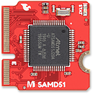
Pick the SAMD51 for an economical and easy-to-use development platform with the convenience of a UF2 bootloader.
| Processor | Clock Speed | Flash | RAM | Other Features |
|---|---|---|---|---|
| ARM Cortex-M4F | 120MHz | 1MB | 256kB SRAM | Up to 6 SERCOM interfaces |
nRF52840 Processor Board
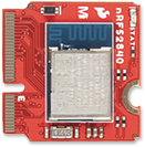
Go for the nRF52840 from Nordic Semiconductor for a union of an ARM Cortex-M4 CPU and 2.4 GHz Bluetooth transceiver.
| Processor | Clock Speed | Flash | RAM | Other Features |
|---|---|---|---|---|
| ARM Cortex-M4 | 64MHz | 1MB | 256kB SRAM | Bluetooth 5 and mesh network capabilities |
STM32 Processor Board
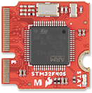
Use the STM32F405 Processor with its high-performance ARM® Cortex®-M4 32-bit RISC core running up to 168MHz.
| Processor | Clock Speed | Flash | RAM | Other Features |
|---|---|---|---|---|
| ARM Cortex-M4 | 168MHz | 1MB/16MB (external) | 192kB of SRAM | 3 low-power operation modes |
STM32WB5MMG Processor Board
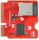
The STM32WB5MMG Processor combines a pair of Arm® Cortex® processors; a Cortex-M4 and a Cortex-M0. The module's radio is Bluetooth® Low Energy 5.3, Zigbee® 3.0, and OpenThread certified.
| Processor | Clock Speed | Flash | RAM | Other Features |
|---|---|---|---|---|
| ARM Cortex-M4 & Cortex-M0 | 64MHz (typ.) | 1MB/16MB (external) | 256kB of SRAM | Matter capable |
Alorium Sno M2 Processor Board
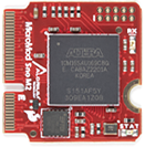
Snō's FPGA provides a reconfigurable hardware platform that hosts an 8-bit AVR instruction set, compatible with the ATmega328, making Snō fully compatible with the Arduino IDE.
| Processor | Clock Speed | Flash | RAM | Other Features |
|---|---|---|---|---|
| Intel® MAX® 10 FPGA | 16/32MHz | 32KB | 2KB of SRAM | Arduino IDE Programmable, Configurable with custom Xcelerator Blocks (XBs) |
MicroMod DIY Carrier Kit
The great thing about open source is that while SparkFun has designed our own MicroMod carrier boards, that does not stop you from creating your very own MicroMod carrier board.
The MicroMod DIY Carrier Kit includes five M.2 connectors, screws, and standoffs so that you can get all the special parts you may need to make your own carrier board.
See the Carrier Kit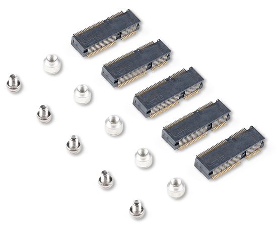
MicroMod Resources
Getting Started with MicroMod
October 21, 2020
Dive into the world of MicroMod - a compact interface to connect a microcontroller to various peripherals via the M.2 Connector!
Designing with MicroMod
October 21, 2020
This tutorial will walk you through the specs of the MicroMod processor and carrier board as well as the basics of incorporating the MicroMod form factor into your own PCB designs!
Technical Specifications
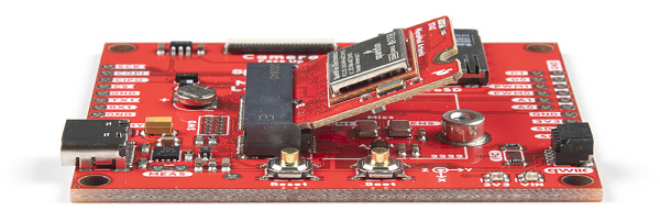
Connections
MicroMod is a compact interface created to connect a microcontroller to various peripherals. You can generally think of the MicroMod system as a "brain" plugging into a "carrier board." A MicroMod processor board is approximately 22x22 mm, and can insert into any MicroMod carrier board. Whereas the original M.2 standard was designed for swapping out peripherals (a user could swap one solid state hard drive for a larger one, for example), the MicroMod standard is designed for swapping out controllers. For example, a user can start with a powerful processor, and then change to a low power controller to extend battery life.
MicroMod M.2 pinout
| AUDIO | UART | GPIO/BUS | I2C | SDIO | SPI0 | Dedicated |
| Function | Bottom Pin |
Top Pin |
Function | ||||||
|---|---|---|---|---|---|---|---|---|---|
| (Not Connected) | 75 | GND | |||||||
| 3.3V | 74 | 73 | G5 / BUS5 | ||||||
| RTC_3V_BATT | 72 | 71 | G6 / BUS6 | ||||||
| SPI_CS1# | SDIO_DATA3 (I/O) | 70 | 69 | G7 / BUS7 | |||||
| SDIO_DATA2 (I/O) | 68 | 67 | G8 | ||||||
| SDIO_DATA1 (I/O) | 66 | 65 | G9 | ADC_D- | CAM_HSYNC | ||||
| SPI_CIPO1 | SDIO_DATA0 (I/O) | 64 | 63 | G10 | ADC_D+ | CAM_VSYNC | |||
| SPI COPI1 | SDIO_CMD (I/O) | 62 | 61 | SPI_CIPO (I) | |||||
| SPI SCK1 | SDIO_SCK (O) | 60 | 59 | SPI_COPI (O) | LED_DAT | ||||
| AUD_MCLK (O) | 58 | 57 | SPI_SCK (O) | LED_CLK | |||||
| CAM_MCLK | PCM_OUT | I2S_OUT | AUD_OUT | 56 | 55 | SPI_CS# | |||
| CAM_PCLK | PCM_IN | I2S_IN | AUD_IN | 54 | 53 | I2C_SCL1 (I/O) | |||
| PDM_DATA | PCM_SYNC | I2S_WS | AUD_LRCLK | 52 | 51 | I2C_SDA1 (I/O) | |||
| PDM_CLK | PCM_CLK | I2S_SCK | AUD_BCLK | 50 | 49 | BATT_VIN / 3 (I - ADC) (0 to 3.3V) | |||
| G4 / BUS4 | 48 | 47 | PWM1 | ||||||
| G3 / BUS3 | 46 | 45 | GND | ||||||
| G2 / BUS2 | 44 | 43 | CAN_TX | ||||||
| G1 / BUS1 | 42 | 41 | CAN_RX | ||||||
| G0 / BUS0 | 40 | 39 | GND | ||||||
| A1 | 38 | 37 | USBHOST_D- | ||||||
| GND | 36 | 35 | USBHOST_D+ | ||||||
| A0 | 34 | 33 | GND | ||||||
| PWM0 | 32 | 31 | Module Key | ||||||
| Module Key | 30 | 29 | Module Key | ||||||
| Module Key | 28 | 27 | Module Key | ||||||
| Module Key | 26 | 25 | Module Key | ||||||
| Module Key | 24 | 23 | SWDIO | ||||||
| UART_TX2 (O) | 22 | 21 | SWDCK | ||||||
| UART_RX2 (I) | 20 | 19 | UART_RX1 (I) | ||||||
| CAM_TRIG | D1 | 18 | 17 | UART_TX1 (0) | |||||
| I2C_INT# | 16 | 15 | UART_CTS1 (I) | ||||||
| I2C_SCL (I/0) | 14 | 13 | UART_RTS1 (O) | ||||||
| I2C_SDA (I/0) | 12 | 11 | BOOT (I - Open Drain) | ||||||
| D0 | 10 | 9 | USB_VIN | ||||||
| SWO | G11 | 8 | 7 | GND | |||||
| RESET# (I - Open Drain) | 6 | 5 | USB_D- | ||||||
| 3.3V_EN | 4 | 3 | USB_D+ | ||||||
| 3.3V | 2 | 1 | GND | ||||||
| Signal Group | Signal | I/O | Description | Voltage | Power | 3.3V | I | 3.3V Source | 3.3V |
|---|---|---|---|---|
| GND | Return current path | 0V | ||
| USB_VIN | I | USB VIN compliant to USB 2.0 specification. Connect to pins on processor board that require 5V for USB functionality | 4.8-5.2V | |
| RTC_3V_BATT | I | 3V provided by external coin cell or mini battery. Max draw=100μA. Connect to pins maintaining an RTC during power loss. Can be left NC. | 3V | |
| 3.3V_EN | O | Controls the carrier board's main voltage regulator. Voltage above 1V will enable 3.3V power path. | 3.3V | |
| BATT_VIN/3 | I | Carrier board raw voltage over 3. 1/3 resistor divider is implemented on carrier board. Amplify the analog signal as needed for full 0-3.3V range | 3.3V | |
| Reset | Reset | I | Input to processor. Open drain with pullup on processor board. Pulling low resets processor. | 3.3V |
| Boot | I | Input to processor. Open drain with pullup on processor board. Pulling low puts processor into special boot mode. Can be left NC. | 3.3V | |
| USB | USB_D± | I/O | USB Data ±. Differential serial data interface compliant to USB 2.0 specification. If UART is required for programming, USB± must be routed to a USB-to-serial conversion IC on the processor board. | |
| USB Host | USBHOST_D± | I/O | For processors that support USB Host Mode. USB Data±. Differential serial data interface compliant to USB 2.0 specification. Can be left NC. | |
| CAN | CAN_RX | I | CAN Bus receive data. | 3.3V |
| CAN_TX | O | CAN Bus transmit data. | 3.3V | |
| UART | UART_RX1 | I | UART receive data. | 3.3V |
| UART_TX1 | O | UART transmit data. | 3.3V | |
| UART_RTS1 | O | UART ready to send. | 3.3V | |
| UART_CTS1 | I | UART clear to send. | 3.3V | |
| UART_RX2 | I | 2nd UART receive data. | 3.3V | |
| UART_TX2 | O | 2nd UART transmit data. | 3.3V | |
| I2C | I2C_SCL | I/O | I2C clock. Open drain with pullup on carrier board. | 3.3V |
| I2C_SDA | I/O | I2C data. Open drain with pullup on carrier board | 3.3V | |
| I2C_INT# | I | Interrupt notification from carrier board to processor. Open drain with pullup on carrier board. Active LOW | 3.3V | |
| I2C_SCL1 | I/O | 2nd I2C clock. Open drain with pullup on carrier board. | 3.3V | |
| I2C_SDA1 | I/O | 2nd I2C data. Open drain with pullup on carrier board. | 3.3V | |
| SPI | SPI_COPI | O | SPI Controller Output/Peripheral Input. | 3.3V |
| SPI_CIPO (I) | I | SPI Controller Input/Peripheral Output. | 3.3V | |
| SPI_SCK | O | SPI Clock. | 3.3V | |
| SPI_CS# | O | SPI Chip Select. Active LOW. Can be routed to GPIO if hardware CS is unused. | 3.3V | |
| SPI/SDIO | SPI_SCK1/SDIO_CLK | O | 2nd SPI Clock. Secondary use is SDIO Clock. | 3.3V |
| SPI_COPI1/SDIO_CMD | I/O | 2nd SPI Controller Output/Peripheral Input. Secondary use is SDIO command interface. | 3.3V | |
| SPI_CIPO1/SDIO_DATA0 | I/O | 2nd SPI Peripheral Input/Controller Output. Secondary use is SDIO data exchange bit 0. | 3.3V | |
| SDIO_DATA1 | I/O | SDIO data exchange bit 1. | 3.3V | |
| SDIO_DATA2 | I/O | SDIO data exchange bit 2. | 3.3V | |
| SPI_CS1/SDIO_DATA3 | I/O | 2nd SPI Chip Select. Secondary use is SDIO data exchange bit 3. | 3.3V | |
| Audio | AUD_MCLK | O | Audio master clock. | 3.3V |
| AUD_OUT/PCM_OUT/I2S_OUT/CAM_MCLK | O | Audio data output. PCM synchronous data output. I2S serial data out. Camera master clock. | 3.3V | |
| AUD_IN/PCM_IN/I2S_IN/CAM_PCLK | I | Audio data input. PCM syncrhonous data input. I2S serial data in. Camera periphperal clock. | 3.3V | |
| AUD_LRCLK/PCM_SYNC/I2S_WS/PDM_DATA | I/O | Audio left/right clock. PCM syncrhonous data SYNC. I2S word select. PDM data. | 3.3V | |
| AUD_BCLK/PCM_CLK/I2S_CLK/PDM_CLK | O | Audio bit clock. PCM clock. I2S continuous serial clock. PDM clock. | 3.3V | |
| SWD | SWDIO | I/O | Serial Wire Debug I/O. Connect if processor board supports SWD. Can be left NC. | 3.3V |
| SWDCK | I | Serial Wire Debug clock. Connect if processor board supports SWD. Can be left NC. | 3.3V | |
| ADC | A0 | I | Analog to digital converter 0. Amplify the analog signal as needed to enable full 0-3.3V range. | 3.3V |
| A1 | I | Analog to digital converter 1. Amplify the analog signal as needed to enable full 0-3.3V range. | 3.3V | |
| PWM | PWM0 | O | Pulse width modulated output 0. | 3.3V |
| PWM1 | O | Pulse width modulated output 1. | 3.3V | |
| Digital | D0 | I/O | General digital input/output pin. | 3.3V |
| D1/CAM_TRIG | I/O | General digital input/output pin. Camera trigger. | 3.3V | |
| General/Bus | G0/BUS0 | I/O | General purpose pins. Any unused processor pins should be assigned to Gx with ADC + PWM capable pins given priority (0, 1, 2, etc.) positions. The intent is to guarantee PWM, ADC and Digital Pin functionality on respective ADC/PWM/Digital pins. Gx pins do not guarantee ADC/PWM function. Alternative use is pins can support a fast read/write 8-bit or 4-bit wide bus. | 3.3V |
| G1/BUS1 | I/O | 3.3V | ||
| G2/BUS2 | I/O | 3.3V | ||
| G3/BUS3 | I/O | 3.3V | ||
| G4/BUS4 | I/O | 3.3V | ||
| G5/BUS5 | I/O | 3.3V | ||
| G6/BUS6 | I/O | 3.3V | ||
| G7/BUS7 | I/O | 3.3V | ||
| G8 | I/O | General purpose pin | 3.3V | |
| G9/ADC_D-/CAM_HSYNC | I/O | Differential ADC input if available. Camera horizontal sync. | 3.3V | |
| G10/ADC_D+/CAM_VSYNC | I/O | Differential ADC input if available. Camera vertical sync. | 3.3V | |
| G11/SWO | I/O | General purpose pin. Serial Wire Output | 3.3V |