
As an engineer at SparkFun, it's a given that I'll be using CadSoft Eagle on a regular basis. When I started here in September, I considered myself proficient, having designed a number of PCBs over the years. But I've also come to better terms with Eagle, learned more of its inner workings, and picked up some additional tricks.
I thought there would be value in sharing some of what I've learned, and how it's been useful.
The Problem
I was designing a new board, and wanted to use a part that had been used on a previous board. I had the files for the original board, but I didn't have the library for the part. Ideally, I'd be able to extract the part from the schematic, and get it into the SparkFun libraries, without having to redraw it from scratch.
A part can get stranded in the schematic for several reasons - the most likely reason is that the original designer created the part in a local library, and never merged that library with the official ones.
(How to avoid using parts that aren't in the library to begin with? Map the libraries directory to only use the right ones - in my case, that's my local copy of the SparkFun-Eagle-Libraries Git repository. Don't forget to sync the repository frequently.)
Where to Begin?
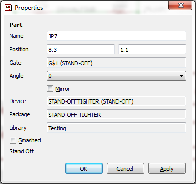
So how can you even tell what library a part is from? In the schematic or PCB editor, use the info tool.
Select the tool, then click on a part. The dialog that opens has a note indicating the library. In my case, it was something like "local-temp." Not a library present on my PC.
A Puzzle
So wait - if the library isn't present on my PC, how can I use parts from it?
This was one of the biggest Eagle mysteries to me at the time. I didn't have a clear picture of how Eagle handled libraries and components. I knew that if I modified a part in a library, I needed to use the "update" option to get the revised part to show up in boards that used it.
Some Insight
I asked SFUptownMaker about my situation, and he shared some useful information, which helped me piece together a much clearer picture of how Eagle handles the libraries.
In software terminology, Eagle uses a "copy by value" operation when a component is added to a design. The information for that component in the library is copied into the design files, in its entirety. Everything defined in the component editor comes along - the schematic symbol, all of the packages, and the data that binds the pins on the symbol to the pads of the package.
At the moment the part is added, it's essentially a snapshot of that part frozen in time at that instant. If the library changes, boards that use it have to explicitly acquire the changes, using the update command.
(This would be opposed to "copy by reference," in which the board files refer back to the library version of the data. If the library changed, the boards would pick up the change automatically. The board files then also become dependent on the library files. If I had a board file, but didn't have all of the libraries it used, it would be useless. Copy by value allows the board files to travel by themselves, independent of the libraries.)
Knowing how components trickle down from the library into the board files is useful, and explains how I got into this situation. However, I still needed to get information to flow backwards, uphill, from the board files to the libraries.
Lifting The Hood
This is where we have to take this well reasoned approach off-road, and use the tools in a way they weren't intended.
Eagle 6 marked the change from proprietary binary file formats to XML. XML is a more general derivative of HTML. Where HTML describes the layout of text and graphic elements on a webpage, XML is a generic means that can be used to specify any data - in this specific case, PCB related data. A specific dialect is defined using a schema, the grammatical rules that describe the statements used in a particular application.
CadSoft haven't published their schema, but by opening the files in a text editor (I'm using Notepad++, which has XML language support, and can roll up and match tags), it becomes apparent that the files use a reasonably clear dialect of XML.
Tags contain simple English statements, and they're organized sensibly, with different sections for each type of data stored. Each section is a list of a specific type of data contained within the file. If you're familiar with Eagle, you probably already have a sense of how different items relate - a device contains a symbol and packages, a schematic contains symbols and nets, and a PCB file contains packages and traces.
Back On Task
To return to the mission we're on here, we want to get a component that exists in a schematic, and move it to a library.
Looking in the schematic file of the component I'm working with, I have to work backwards a few steps, to get back to the library data.
- Using the name that was displayed in the info box, I search for that name. Towards the end of the file, I find an instance tag that contains the name.
- There is also a `part tag with the same name. This tag contains a reference to the library, and the specific device within that library.
- I search for the name of that library, and find a large tag in the
<libraries>section of the file. - There are several sections within the library the specify the data for the part. It's actually easier to make sense of the by working backwards.
- Towards the bottom of the library is a section for
<devicesets>. A deviceset corresponds to the device section of the library editor. It contains a number of gates. Each gate references a symbol, and a number of devices, each referencing a package. <Symbols>are the portion of the component used on the schematic. A device can contain multiple symbols, such as each of the gates contained within a logic IC.<packages>define the footprint of the part as used on the PCB - including the copper, holes, and silkscreen data. A device set may also contain multiple packages, perhaps for DIP and SMT variants of the same component.
- Towards the bottom of the library is a section for
To get the part from the schematic to the library, I open both files in separate tabs of my text editor. I copy and paste the deviceset tag, the symbols referenced by it's gate list, and the package tags that it lists. Each of these is placed at the bottom of the respective sections in the destination file - <devicesets>, <symbols>, and <packages>.
After cutting and pasting, I save and close the XML file. I then open it in the Eagle library editor. If I got any tags out of order, Eagle will helpfully tell me the line number that is causing the problem.
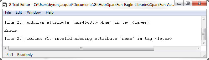
Sometimes it takes a couple of tries to get everything right. Opening the library in the editor appears to be a fairly decent judge as to whether the XML is properly formed.
I'm not especially confident that Eagle will behave gracefully if you have edited a file in both a text editor and Eagle itself. I'd imagine that one would overwrite the other. For safety's sake, I prefer to not have them both open simultaneously.
Epilog
While it makes my schematic-to-library part translation possible, there are some other advantages to using XML for storing the files.
XML is great for storing PCB files in a text based revision control system, such as Git. At SparkFun, we're no longer just pushing opaque chunks of binary PCB data into the system - we can see meaningful deltas in the RCS, and even use a text editor to resolve merge conflicts.
It's not as great as a true graphical diff tool would be, but it's a lot more useful than just storing and comparing opaque binary blobs.
There are some situations where it's easier and more precise to manually edit the text of an XML file than it is to arrange items in a GUI.
Finally, since the file format is reasonably transparent, we can write new software tools around it. We have several in-house tools that take advantage of this, including the SVG importer.
Like a lot of things in Eagle, there may be more than one way to reach a result. I won't be surprised if someone responds to this post, and tells me that I just needed to look in menu X, or enter non-obvious command Y.


Alright, I've held my tongue long enough.
What is it with SparkFun and Eagle? I really feel that SparkFun needs to drop its Eagle 'support' and start supporting KiCAD. As a site that prides itself on open source materials, I could never understand why everything is designed using freemium software when there is a better, as easy to use, open source alternative. On the surface, KiCAD is as easy to use as Eagle. However you can dive into the deep end and get functionality that almost rivals that of something like Altium Designer. Learning Eagle is a dead end. The work flow that Eagle implements doesn't translate well to other EDAs and you're severely limited with the free version of Eagle.
SparkFun's New Years resolution should be to kick Eagle to the curb...
Not to worry - others have wagged that tongue before :)
While I agree that it would be nice (and that's an understatement) for SparkFun to support open source solutions even further, I don't think that dropping support for Eagle would be a smart move. If nothing else, you can easily go from Eagle to KiCAD, the other way around is not as easily done (and to the end-user, it really doesn't matter who is to blame for that).
KiCAD is making great strides and I'm sure SFE's engineers continually review what the best product is - not only for everyday work, but also for making material available publicly. Think evolution, rather than revolution.
In the mean time, it helps more to promote KiCAD than it does to criticize Eagle ( and really, we've already had a browser war thread in the comments recently, I don't think a repeat in the domain of EDAs would be fun ;) )
For example, what ways can you think of in KiCAD to accomplish the basic premise of this article; How do you get a component from an existing schematic/board into a library?
because eagle has been for many many years the professionals choice when they dont want to spend any money there not going to up and change just because some other tool may or may not be better at the time but i have to disagree about KiCAD i find it to be overly simplified where it should not be and overly complicated where it should be easy and it crashes too much im also not an altium fan, i have to use it for work and it was back in the day the best tool you can use but they have lagged behind other free suits
What then would you recommend? I like Altium and it seems to flow reasonably well, though some things (can't think of specific examples just at the moment), don't seem to have kept pace with the general software world. I've tried Eagle and it just seems so darn foreign compared with other tools I've used.
I have to +1 this. I started with Eagle because that is what SF promotes (and provides tutorials for!). I really appreciate the support they provided when I was starting out, but now that I use KiCad (Had to switch for commercial application) I wish I had started there. No restrictions on boards, open source, and has the option to use a single schematic with multiple board layouts (big seller for me). So you can design an Arduino clone in a schematic, and then choose to make both a SMD and Through Hole version just by selecting different footprints! I used this recently with a power board I designed, started with TO-220 transistors and switched to SMD D2Pak with the same initial schematic.
The XML schema included in every installation of EAGLE. You can find it in the Doc folder of your installation, the file is called eagle.dtd.
As already mentioned you can extract all of the libraries from a board schematic pair by running the exp-lbrs.ulp that comes with EAGLE. In V6 you can run it directly by going File -> Export -> Libraries.
hth,
Jorge Garcia Cadsoft Computer
This is a great explanation of the inner-workings of Eagle lbrs! I've run into this very problem myself. It turns out, if you run a built-in ULP, you can extract all the components from your schematic or board directly into their original respective libraries (or merge them into one unified library).
That would be: from your board or schematic view File -> Run (ULP) -> Open exp-lbrs.ulp -> Select export path -> Select whether to merge libraries -> Hit OK
Then, you can import the resultant libraries, pick them apart, reorganize them, etc. Note: older versions of eagle may have "exp-project-lbr.ulp" instead.
I think it's important to understand the nuances of the xml involved in storing library data and the open possibilities for creating those custom scripts or programs to modify components. So Byron's tutorial is still a great resource, kudos!
I just gave that a try, and it works. As with a lot of things (particularly in Eagle), there is often more than one solution to a problem.
It may not entirely avoid the need to merge with an external library (it looks like it only extracts the components used on the schem), but it certainly helps distill the tags needed by the library from the rest of the schem to make the merge easier.
Combine that with the newly found schema, and a decent validating XML editor, and it's a lot easier.
Absolutely. I definitely don't want to discredit having a thorough understanding of the schema, or XML in general. Pairing those abilities, like you said, reduces the hair-pulling moments substantially: knowing both would almost certainly bump up productivity.
And another Schematic/PCB editor to consider is DesignSpark PCB. It isn't open source, but it is free, without limits on board size or commercial use.
I've also used a higher-end commercial package at a past employer, and free ExpressPCB in the past for prototypes.
ExpressPCB is easy to use, but while it is free, it doesn't output gerbers, so you are limited in who you could use for the fabrication unless you "buy" gerbers for your design from ExpressPCB. It is also more limited in other respects.
I've found DesignSpark PCB to be roughly comparable to the commercial package I had used. It has its share of annoyances, but some really nice features, too. The biggest hindrance for a beginner is the schematic library symbols for many common parts tend to be rectangles, with properly numbered pins, but not the more common functional symbols like triangle for op amp, etc. You can add your own symbols to the library, though, and easily associate them with the components. (I plan to share a library of such symbols I've created, in order to make it easier for (I think) the majority of us who prefer the functional symbols.) The other downside is that its only native version is for Windows. The other up-side, though, is that it has footprints for a very large library of parts, and in many cases has multiple footprints available for the same package, following IPC standards for dense, normal, and loose (hand-solder) designs.