Creating a Custom Tilt Sensor
While designing our new Simon Tilts Through Hole Soldering Kit, we ultimately found that the best solution for the tilt sensor involved creating a custom plastic part. Here is the story of this project - including a couple interviews with the people that helped us along the way.

For this project we worked with a local company in Longmont, Mountain Molding. Their technicians, Todd and Warren, were kind enough to let us hang out and ask a few questions. Here's a video we shot during our visits to their facility.
ReplaceMeOpen
ReplaceMeClose
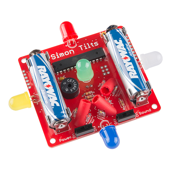
The inspiration for this project came from one of my first memories at SparkFun. It was my second day, and I was testing some accelerometers. I was quite awestruck as I waved the circuit board up and down and the numbers changed. "Wow," I thought, "this is cool!" I was amazed that movement could be so easily transformed into streaming data on a computer screen. And all because of a tiny black box on a little red board. Many years and projects later I remembered that moment, and it inspired me to create a game celebrating the fun connection between motion and electronics. The end result: our new Simon Tilts Through Hole Soldering Kit.
Early on, I knew the game was going to involve patterns of movement and play similar to how Simon Says works, but I wasn't entirely sure how the position sensing was going to work. This challenge proved to be more difficult than one might expect.
Having such a fond memory of the ADXL335 Accelerometer, it's kind of sad that we ultimately didn't use it in the design. The desire to keep the kit 100% PTH was too important, and so another solution was necessary. We tried metal ball tilt sensors, hall effect sensors and magnets, and even two tilt-a-whirls, but none of the prototypes worked as well as we wanted. We eventually came up with a solution that involved a similar mechanical movement to the metal ball tilt sensor, but didn't rely on the physical weight of the ball to make the connection on the switch. We decided to use an infrared emitter and detector to detect the position of the ball inside the cylinder. If you position them in a certain way with 45 degree angles, then the balls will fall in a unique pattern for all 6 positions.
This would prove to be much more reliable, easy to assemble and would have the added benefit of exposing the mechanics to the player - hopefully encouraging more understanding of how movement could be translated into data. The difficult part of this solution was the fact that such a cylinder did not exist, and so our project expanded into the wonderful world of injection molding!
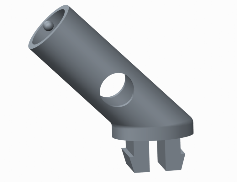
After hashing out some drawings on my dry erase board and in Google SketchUp, I talked to our in-house mechanical engineer at the time, Paul Smith. He generously offered to give me a quick rundown of Creo Parametric to create a more polished design. After a few hours of monkeying around with sketches, extrudes, revolves, and mirrors we had the following version 1:
At the time, we did not have a 3D printer with high enough resolution to prototype our design, so lucky for us we had some friends that did. Thanks to Modular Robotics we were able to fine tune the design before committing to a tool with Mountain Molding.
The most challenging feature of the design was the snap-in legs. They were intended to mate with a square cut-out of a standard thickness PCB. The idea was that the assembler could push the part down into the cut-out and the legs would bend in temporarily. When the part was pushed in all the way, the legs would then release back into their natural position and the slight ledge on the end of the leg would hold the part in place. The really tricky part of this process is that the leg must be thin enough to flex, but strong enough to not break off. Also, the size of the slight ledge on the end of the leg had to extend far enough to hold position, but not too far as to require a large amount of displacement during insertion.
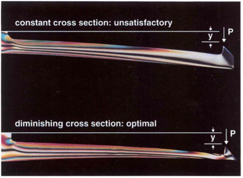
During prototyping with Modular Robotics, we simply tried a few different leg thicknesses and eventually found a good combination. When we started working with the tool maker at Mountain Molding, Todd, he wanted to refine the snap in legs even more and directed us to a very informative technical document on snap fit designs. After just some very slight tweaking, we finally found a balance of flex and strength that worked for the application and worked for the tool. Here's is a screen shot of the final design in Creo Parametric. Notice how the snap fit legs are slightly thinner than our first version and now have a taper.
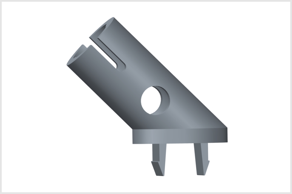
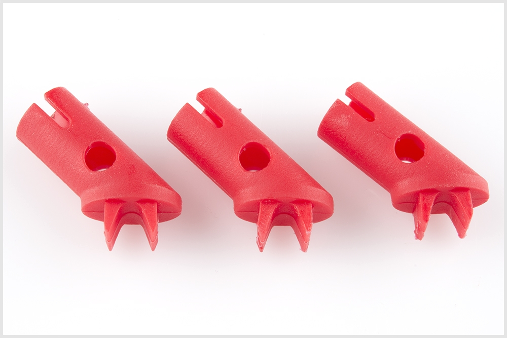
And here they are in all their glory!
We don't have too many projects around here that involve injection molding, but we sure find it interesting and exciting. Please let us know if you have any fun projects on the rise or share about any custom parts you've made in the past. Also, we hope you enjoy the new Simon Tilts!


Really cool, and really good to know there's a local place for injection molding. I'm currently prototyping several pieces on a 3D printer to test for fit, but will need someplace to mass produce, should I be able to get it to that stage. Thanks for sharing not just the the process, but also the local businesses who helped make it possible.
Hey HelicopterGuy, You are welcome. If you are local, I would recommend meeting up with MM. You can learn a lot if you go take a tour and tell them about your project.
Any chance your prototype parts are going to show up at AVC?
Hey Pete - The parts I'm prototyping at the moment are completely mechanical, non-arduino (or beagleBone, or anything else) driven components for a kids' educational toy. That's not to say they can't show up at the AVC, or that I won't be showing up with new and different parts. But I will definitely be showing up at the AVC again!
And yes, I will definitely meet up with MM. I've wanted to keep production of my pieces in the US, and if I can keep them in Colorado, even better.
I remember helping a student make a custom distance sensor using only a Arduino, a big speaker, and a mic. Amazingly it was off by ~6inches at 200+ feet.
Hey Tech Geek, thanks for sharing. Sounds cool. And that precision ain't that bad! This sounds like it would make for a fun classroom experiment. Did you happen to document your hookup or take any pictures?
Also, were you able to use a square wave off of an Arduino pin to create the sound? I have found that analyzing sound with a mic and a micro can prove to be difficult. Were you processing the raw AC signal from the mic? We have recently tried to make detecting sound a bit easier with our new Sound detector. I'm not sure if our sound detector could be used in this way to detect a specific signal, but if you were in a quiet environment, then maybe it would work.
I lost most documentation in a house fire. Although there might be something hidden in my Email history.
I do remember pretty much everything that SFE would want to know if they were interested in posting about it on the blog.
Also the project was used to measure how deep a 6" wide well pipe was. So the echo was contained quite well
Hi Pete, How long did the mold design and mold making process take and about how much did it cost?
Thanks, Scott
Hi Scott, For a similar plastic part (in size and complexity), you can expect to pay 6-8K for tooling. The complexity is a huge factor in cost. Because our tilt part has a cavity, it required a 3-part tool: Two sides that slide outwards and a core pin.This basically doubled the cost of the tool. If you have a part that can be made with a 2-part tool, it would be more in the 3-5K range.
About time commitment, I think you can expect that you and the tool maker will need to adjust the part a few times to get the design ready for production. So if you were really quick, and the molding company was really responsive (which was the case with MM), then you may be able to get from idea to parts in 4-6 months. I'm sure a more experienced mechanical engineer would have spent less time designing than I did, and they may have avoided any necessary revisions.
I asked Modular Robotics to 3D print our first prototype in January of 2013, and the finished product went live on January 9th, 2014. So all in all, it took about a year. Although we did have the parts in hand by Dec 2nd, so design, tooling and manufacturing was more like 11 months total. I would also like to mention that during the past year this was not my top priority project. I am the quality control manager here at SparkFun, so quite often my immediate responsibilities would kick Simon Tilts to the back burner.
Also, I would like to mention that it was really great working with Mountain Molding. I'm sure they would be very happy to answer any more questions you may have. You can contact them here: http://www.mountainmolding.com/contactus.php