
This post is about a model computer that Bell Labs released in 1968 for use in high schools – CARDIAC (CARDboard Illustrative Aid to Computation). The central concepts are the same, but the technology of the day was a little less mature.
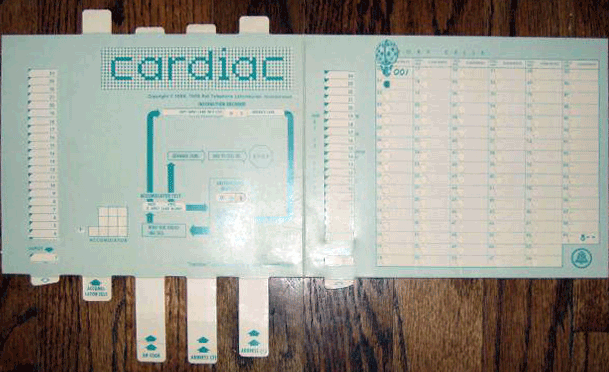
Photo is a modified version found at drexel.edu
Here is a video Bell Labs released in conjunction with CARDIAC. It gives one a feeling for the state of computing in that day. I especially like the schematic capture tool they show around 9:19. Wish we had that tech to use here at SparkFun.
Von Neumann Architecture
In 1945, mathematician and physicist John von Neumann described the computer architecture used in CARDIAC (and many other computers) for the United States Army. The von Neumann model consists of five parts: a control unit, a processing unit, memory, input and output.

Recreation of diagram in the CARDIAC manual
PROGRAM UNIT
The program unit, also known as the control unit, contains all of the parts required to control the computer. The creators of CARDIAC refer to this as the program unit. Inside are special pieces of memory called registers, a finite state machine, multiplexers, and other pieces that this discussion will largely abstract out. It is left as an exercise to the the reader to dig deeper than the level presented here. The main concept is the finite state machine takes a set of inputs, like the instruction register and a clock signal, and decides what to do next. The control unit is also responsible for managing the program counter register. This register keeps track of where the next instruction to fetch lives.
ACCUMULATOR
The processing unit consists mainly of an ALU (Arithmetic and Logic Unit). The ALU is responsible for basic arithmetic functions like addition and subtraction. The ALU is also often responsible for basic logic operations like bit-wise AND, OR, and NOT. The CARDIAC computer is very basic and cannot do these logic operations, but can do shifting and comparison. An accumulator is one form of ALU configuration. The accumulator is a special register that stores the results of the ALU. This simplifies the ISA (Instruction Set Architecture).
MEMORY
Memory is is a set of storage elements and a few registers to assist in communicating with the storage. The MAR (Memory Address Register) stores the location or address in memory that is to be read or written. The MDR (Memory Data Register) holds the data to be written to memory or the data read from memory.
Now is a great time to talk about a key difference between CARDIAC and traditional computers. Traditional digital computers use tubes or transistors to set the state of the computer. They typically can only have two states – off or on; high or low. This is referred to as binary. Since this is a cardboard illustrative aid, and not a real computer, it’s not troubled by these implementation details. CARDIAC is a human friendly base 10 (decimal) machine. Rather than using binary bits, CARDIAC uses decimal digits.
The MAR is two digits. CARDIAC can thus address 102 or 100 addresses. Not all machines have the memory they are able to address, but in this case we do, all 100 three-digit words! Each memory cell is three digits, and so is the MDR. The accumulator is four digits to accommodate overflow. All four digits are kept in the accumulator until stored, when the most significant digit is dropped. Negative numbers are simple negative numbers here. Don't worry about how the computer encodes them since CARDIAC is really pencil and paper.
INPUT
Input comes in many forms on real computers. Any peripheral one can imagine can be used as input. Some of the more common types of input are the keyboard, mouse, disk, scanner, etc. All of these types of inputs are eventually converted into a format that the processor can work with. In the case of CARDIAC, this is a list of three-digit numbers. These numbers are composed of two parts. The most significant digit is the opcode (operation code), and the other two digits are operand. In most cases the operand is simply an address. In the case of the shift opcode, the middle digit tells how many digits to shift to the left, and the right-most digit tells how many to shift to the right. The halt opcode ignores the operand.
OUTPUT
Computer output comes in as many forms as inputs. There are monitors, speakers, printers, disks, etc. In CARDIAC, output comes in the form of numbers from -999 to 999. For real world applications each value can be assigned a meaning. For example if one wrote a blackjack game, 20 could mean the computer draws a card, 30 could mean hold, and 40 could mean fold.
RUNNING CODE
When CARDIAC first "powers on," the memory is empty; even the registers are initialized to zero. How does one get a program into memory to run?
The program counter begins at 00. This means that the next instruction to load is in memory at location 00. Thankfully there is an exception to memory being empty at boot. Address 00 is ROM that contains the instruction 001. This discussion cannot proceed without first describing the instruction set, so let me do that here:
| Opcode | Instruction | Description |
|---|---|---|
| 0 | Input | Read next input and store it in memory addr |
| 1 | Clear and Add | Fill acc with contents of memory addr |
| 2 | Add | Add contents of memory addr to value in acc |
| 3 | Test Accumulator Contents | If acc is negative then set PC to operand |
| 4 | Shift | Shift acc left and then right |
| 5 | Output | Write contents of memory to output |
| 6 | Store | Copy acc to memory specified by operand |
| 7 | Subtract | Subtract value in memory from acc |
| 8 | Unconditional Jump | Store PC in addr 99 then set new PC value |
| 9 | Halt and Reset | Stops the machine |
Back to running code... Memory address 00 always contains 001. This can be broken into the opcode and operand (0 01). 0 indicates the input instruction. The operand 01 indicates that the input will be written into memory address 01. When the first instruction 001 is being processed the PC is incremented by one and is now set to 01. The next instruction to process is the one that was just loaded from the input by the previous instruction. Now the computer is running code that the user has specified!
BOOTLOADING
The process briefly described in the previous section is called bootstrapping. It's how you get up and running at boot time. Real programs require more than a single instruction. How would you get more code into a machine? What is the first instruction you would have loaded? How about 002? The program counter is going to increment again while processing your first instruction and be pointing at memory address 02, may as well have something there to run. How about 800? This makes the full program:
001 ;(In ROM)
002 ;(top of input stack)
800
The computer begins with the PC set to 00 & executes the first instruction (001) at address 00. This loads the first input (002) into memory address 01 and increments PC. The computer now sees the instruction 002, so it loads 800 from the input into memory address 02 and increments PC to 02. Memory address 02 contains 800, or jump to address 00, so it sets the program counter to 00 rather than incrementing it. We are now back at our initial state with one very important difference. We have an infinite loop (neglecting some details). This is the core of our bootloader.
Lets assume we are back at PC = 00, but we have 800 stored at address 02. All we have to do now alternate between load instructions and our real program code. For example let the full input stack be:
002
800
010
100
011
200
012
615
013
515
014
900
810
If you start decoding the new instructions you will see that we are loading 100 into memory at address 10, loading 200 into 11, loading 615 into 12, loading 515 into 13, 900 into 14, and the final instruction is 810. When the computer gets here what is it doing? 810 means jump to address 10. But what is at address 10? It's our first real bit of code!. The program has been bootloaded into memory addresses 10 through 14. Here is that listing:
10: 100  ;clear accumulator and load the contents of 00
11: 200  ;add the contents of 00 to the accumulator
12: 615  ;store the contents of the accumulator to memory address 15
13: 515  ;write the value in memory address 15 to the output
14: 900  ;halt and reset
What does this code do? It adds 1 + 1, outputs the results and halts. 13 lines of assembly code to add 1 + 1! This might give some appreciation for how much goes on behind the scenes in computers.
DOING REAL WORK
You may have noticed that this computer can't even multiply. How would you do this? Doesn't 3 * 4 = 3 + 3 + 3 + 3 = 4 + 4 + 4?
Wouldn't that be nice to have a subroutine that could multiply for you and put the result in a predetermined memory address? Did you notice that the opcode 8 stores the current PC into memory address 99? This address is the second address that isn't standard memory. The opcode is always 8. If one were to run 898 from memory address 14 address 99 would store the value 815 and the PC would jump from 14 to 98. Assume the contents of address 98 are something simple like 200. What would this do? First it would increment the accumulator. The PC would then increment to 99. The computer would run the instruction stored there, 815. This would jump back to PC = 15. This is a trivial subroutine that adds one to the accumulator, but you could instead put your subroutine starting at address 90, run 9 interesting instructions before returning to right where you left off.
I encourage you to play around with writing some CARDIAC assembly code. The ISA of the machine in front of you is doing the same basic thing, only it has many more complicated instructions in addition to this simple set of 10. I've written a simulator that you can try running code in. Be warned that there is virtually no error checking, so your code must be decent. If you tell the machine to run an invalid command and it locks up, hit the reset button. The simulator is preloaded with code to count to 10 on the output. Enjoy!
Edit: The old iframe doesn't work due to mixed content (it doesn't use TLS, but our site does). Here is a link to the simulator.
iframe
The source code for the simulator can be found here.


Yup, grade 9 computer class. After school run by the new math teacher - Long hair, tie-dye shirt and beads. We started with CARDIAC, moved on to BASIC on punch cards. I got lucky and the social studies teacher decided to try computer assisted instruction as part of his masters thesis and we got a modem and a IBM Selectric terminal to the local university and I started real programming (got to write some of the course material). Never looked back but it all started with CARDIAC. I made a 4 digit version with more instructions at one point and had the game of NIM running on it. I did write an emulator back then as it took a lot of manipulating to calculate each move. Unfortunately I don't think I kep the programs. I should go through the back of my filing cabinet and wee if by chance... I did buy two new (old) CARDIAC a couple of years back.
The emulator is great. I am going to let my nephew see it and maybe he'll play a bit just for fun. I have often thought of a hardware version but never taken the time to do it so 'Thanks'.
I've also had a hardware version low on my todo list. It would be a fun little project to read the cards, etc. Reliably feeding single cards (pieces of paper) has partially held me back. I'm sure we all remember paper jams at some point in our lives.
When I worked for a composites manufacturing company in Denver, the other part of their business was manufacturing slurry pumps so they had a pretty sizable machine shop with some super old machines. One of their CNC machines used punch cards and little pneumatic pins that would activate electric switches on the other side. Their pump housing design hasn't changed much in 50 years, so as long as that machine kept doing the same operation there was no need to update the punch cards. I definitely wouldn't recommend using pneumatic pins, but I imagine you could make something with a row of phototransistors and a basic feed mechanism (or just keep the cards stationary and move the reader like a scanner); I doubt you'd have to worry about paper jams too much if you use heavy card stock.
This device sent me down the path as a programmer back in the 1970s. Hmm, maybe I can slap something together with an arduino to build an electric version of a CARDIAC.
Edmund Scientific had these for sale two years ago but it looks like they're sold out. Mine is unpunched and still in the envelope. I wonder if I could scan and upload it?
Sorry for taking so long to get back, but AFAIK, a picture of a product is legal to post. Anything we post is licensed Creative Commons. If you are okay with that, I think I could post it to share with those who are interested.