State Machines: blink.ino learns to snooze
A look at implementing the Arduino blink.ino sketch as an explicit state machine. To further explore state machines, an alarm clock state diagram is drawn and implemented.

I'm a big fan of state machines. Almost every Arduino sketch usually ends up with at least one intentional state machine and a bunch of non-intentional state machines as well. Here, I'll introduce the concept of state machines, and apply a state machine to a microcontroller's "Hello world!" blink routine. After that I'll explore some more complicated state machines, such as an alarm clock.
What is a state machine
A 'state' is the condition of a thing at a specific time. Something that can accomplish tasks and that utilizes states at its core is a state machine. They are also known as Finite State Machines (FSM), meaning that we know all possible states of the thing. The key to the state machine is the concept of time and history. The state of the machine is evaluated periodically. Each time it is evaluated, a new state is chosen (which could be the same state again), and the output is presented.
Our newly released servo trigger https://www.sparkfun.com/products/13118 is a good example of a state machine, and was developed with a similar technique. It's a switch case statement under the hood, but with accurate timing added in.
A generic state machine:
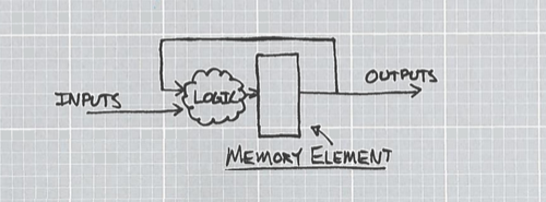
A diagram of a generic state machine. The memory element contains the current state known as the state variable. When the state machine is serviced, the state variable is updated with the value of the next state. Here, the next state is a function of both the current state and some input. The cloud of logic is some system that decides what the next state is to be, or the next state logic.
A simple state machine: The counter
A classic example of a state machine is a counter. For example, a 'for loop' or a 74x4040 logic IC both work as a state machine. Each time the machine is poked, either by the clock line or looping behavior, the state of the memory changes to a new state equaling the old state plus one. The finite set of states it can have is the numbers it can count.
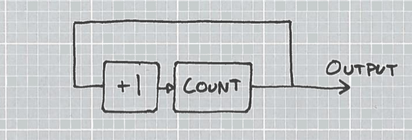
A basic counter expressed as a state machine
Parts of the counter state machine:
- The current state is the value that has been counted.
- The output is the current state.
- The next state logic is whatever the current state is plus 1.
- There are no inputs. In a more advanced diagram, an enable line or reset counter function would be drawn as an input.
The state machine advances at whatever rate it is serviced.
Moore and Mealy state machines.
Digital logic professors love to ask test questions about Moore vs. Mealy and so I have to talk about them. I don't think the distinction makes too much sense while writing state machines in C; it's more of a "how to make logic hardware" distinction. For us, the lesson from Moore and Mealy is that people existed who thought about this stuff and invented ways of notating it. While they targeted logic hardware, we'll target c software.
Moore State Machine
Edward Moore wrote a paper in 1956 (Gedanken-experiments on Sequential Machines) and thus the style of machine is named after him. He says the output is dependent only on the state, and the next state is dependent on the current state (or output), and the input.
Our previous diagram
You can see that no matter what the input state is, the output only depends of the current state contained within the memory element.
Mealy State Machine
Another guy, George Mealy, wrote a paper one year earlier than Moore, entitled A Method for Synthesizing Sequential Circuits, in which he goes into great depths about creating state machines from mathematical functions, and describes those state machine's outputs in terms of their inputs.
To diagram the Mealy machine, the output is made to depend on both the current state and the input. Here, the cloud of next-state logic contains the output logic as well:
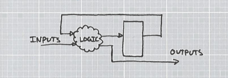
One way of drawing a Mealy machine
It could also be drawn by seperating the cloud into next-state logic and output logic:
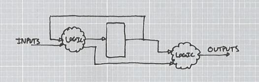
Another way of drawing a Mealy machine
Abstract State Diagrams
So far, we've seen that a state machine has some memory that stores the current state, that it must have come from some state, and that it will go to the next state. Our current diagram doesn't show how it moves through states though. The goal should be to draw a map of the movement between states so we can write code that emulates our design. This is called a state diagram.
This is how I diagram the states of a state machine, using ideas from Moore and Mealy.
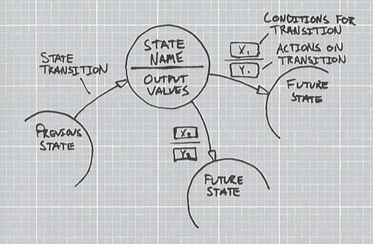
An abstract state diagram
Parts of the diagram:
The circle is the state
The colloquial name of the state is given in the top half of the circle
The output of the state is given in the bottom half of the circle. Sometimes this is explicit, like "X=1," and the state behaves like a Moore, though sometimes it could be "OUTPUT = INPUT" where during that state, make the output equal whatever the input was. In this sense, the machine is very Mealy. I lump the two together for writing C state machines because it doesn't really matter to the C construction of the machine.
The arrow is the state transition path.
The Xs, above the line, are the conditions for that state transition to occur. If the conditions are met, that will be the transition path.
The Ys, below the line, are things that happen during the transition. This concept deviates from the strictly digital logic world of Moore and Mealy and stems from the consecutive execution nature of C. While running a program, it's easy for me to check for the transition conditions and do some one-time action while changing the states, so I put the actions under the conditions.
Always keep in mind that these are abstract representations of code and are a tool for creating higher levels of operation. Put as much detail as you need into the diagramming.
Consider a basic state that can move to a new state.
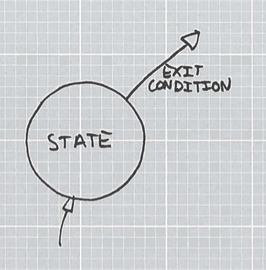
Simple state with incomplete set of state transitions
What happens if the exit condition is not met? I've cheated with my diagram and haven't defined all possible actions of the state. Often I won't quite know the full solution of my program until after the diagrams are made, and I embellish them as I go. With this diagram, I assume that if the conditions are not met, the state will go back to itself.
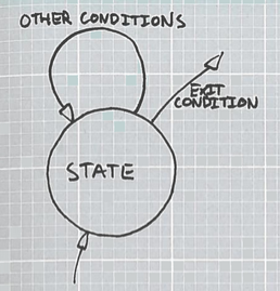
Fully specified state
Here, all possible state transitions are defined.
State diagram of the counter
Check out the behavior of the counter as drawn with a state diagram.
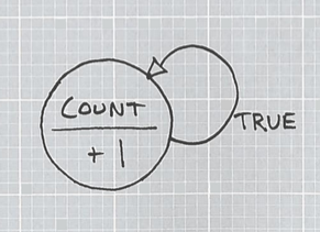
State diagram of a simple counter
Here, all possible states are represented with a single circle. The action of the state is to add one. To determine the next state, it's easy to see that we only have one option, which is to go back to the state we were in.
The blink.ino Sketch
blink_fsm.ino
Let's get out of the theoretic world by re-writing the familiar blink.ino sketch with the behavior and syntax of a state machine, using a switch-case. The example is to light the LED for 1 second, turn it off for 1 second, and repeat. Here there are two states, LED_ON and LED_OFF.
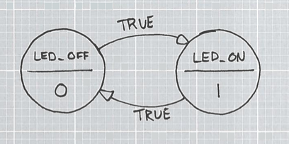
A basic LED toggler
In each state, the LED value is shown under the line. The arrows are each labeled TRUE because no matter what, we'll move to the next state. This state machine doesn't have any inputs. Every second, we'll evaluate the state machine. If the state is 1, the output is 1 and move to the state 0. Here's the C implementation:
Full source file (github): blink_fsm.ino
To make the state machine in C, create a variable that holds the current value of the state, define words for each numeric value that the state can be, and write a switch-case to evaluate the next state.
Defining the states:
//Define the states of the machine
#define LED_OFF 0
#define LED_ON 1
Creating the (global) state variable:
uint8_t fsm_state = LED_OFF;
So far, the state can be one of two options, so the smalles size data type is selected.
The state machine is built in the loop():
void loop(){
  //state machine
  switch (fsm_state)
  {
    case LED_OFF:  //Statements to execute every time LED_OFF is reached
      digitalWrite(13, LOW);
      fsm_state = LED_ON;
      break;
    case LED_ON:   //Statements to execute every time LED_ON is reached
      digitalWrite(13, HIGH);
      fsm_state = LED_OFF;
      break;
    default:
      break;
  }

  delay(1000);              // wait for a second
}
Every time the loop is executed, the state machine is evaluated. The state variable (fsm_state) is global, so it retains the state.
You may notice that every second we wait 1 second and evaluate the state machine. The extra code associated with the processing of the state machine will cause the cycle time to be greater than a second! It will run a little slow. This could be interrupt driven for better accuracy.
blink_fsm_ms.ino
I don't want to have to wait for a whole second. I could be accomplishing other things during that time! I would rather process the state machine at some faster interval, like 1 ms, and stay in a single state 1000 times in order to delay.
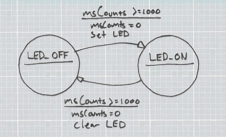
A basic toggler that is clocked faster than the toggle speed.
With this design, I won't leave the state unless the msCounts reaches 1000. The loop is delayed for 1ms instead of 1000ms. When the condition is true for a state transition to occur, the LED state is written and the counter is reset.
Full source file (github): blink_fsm_ms.ino
As before, the same states and state variable is used. The state machine is expanded to provide functionality if and only if the state transition is to occur.
switch (fsm_state)
{
  case LED_OFF:
    //Statements to execute every time LED_OFF is reached
    //Statements to execute when it's time to move to the next state
    if(msCounts >= 1000)
    {
      digitalWrite(13, HIGH);  //Process the next state's function
      fsm_state = LED_ON;
      msCounts = 0;
    }
    break;
  case LED_ON:
    //Statements to execute every time LED_ON is reached
    //Statements to execute when it's time to move to the next state
    if(msCounts >= 1000)
    {
      digitalWrite(13, LOW);  //Process the next state's function
      fsm_state = LED_OFF;
      msCounts = 0;
    }
    break;
  default:
    break;
}
Now, each state only moves if the state transition logic is true, using an "if" statement. Here's where it's obvious how easy it is to add 1-time tasks to the action of transitioning states. They're just added to the "if" statement, and will be executed only when the state moves.
The state machine works but I'm not terribly happy about how it came out. Notice that the LED state is set LOW during the LED_ON state and HIGH during the LED_OFF state. It's easy to run one-time code leaving a state, but not during the entrance of the state. It's counter-intuitive to me and I think it can be made clearer by adding two more states, each that only wait.
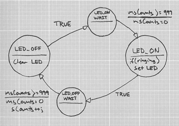
blink_fsm_final
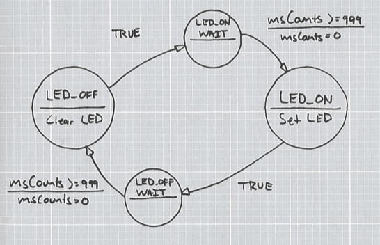
A toggler that uses an additional state to wait for the counter.
Here, the states LED_ON and LED_OFF write to the LED, clear the counter, and move on.
Timing and accuracy side note: The counter has been modified to 999 to account for the extra state, but it doesn't help much. We're getting farther off the faster we run the clock. This is because the time it takes to evaluate the state machine is starting to approach the total time to execute loop() INCLUDING the delay(1); statement.
Full source file (github): blink_fsm_final.ino
First, the extra two states are added to the list of #defines.
//Define the states of the machine
#define LED_OFF 0
#define LED_ON_WAIT 1
#define LED_ON 2
#define LED_OFF_WAIT 3
The state variable is the same so we'll move on to the actual state machine implementation.
//state machine
switch (fsm_state)
{
  case LED_OFF:
    //Statements to execute every time LED_OFF is reached
    digitalWrite(13, LOW);
    fsm_state = LED_ON_WAIT;
    break;
  case LED_ON_WAIT:
    //Statements to execute every time LED_OFF_WAIT is reached
    if(msCounts >= 1000)
    {
      fsm_state = LED_ON;
      msCounts = 0;
    }
    break;
  case LED_ON:
    //Statements to execute every time LED_ON is reached
    digitalWrite(13, HIGH);
    fsm_state = LED_OFF_WAIT;
    break;
  case LED_OFF_WAIT:
    //Statements to execute every time LED_ON_WAIT is reached
    if(msCounts >= 1000)
    {
      fsm_state = LED_OFF;
      msCounts = 0;
    }
    break;
  default:
    break;
}
We see that the extra states have become extra cases in the switch statement. States that always move on simply assign the next state to the state variable. The delay states check the counts before assigning a new state, thus retaining the state they were in.
More timing side notes: Run the msCounts incrementer with a 1 ms timer Interrupt Service Routine (ISR) instead. Meanwhile, loop the FSM as fast as possible. This will correct timing. Keep in mind that if the code execution time between ISR calls (the state machine processing time) is longer than the ISR call interval, the program will most likely lock up.
"Yeah, so what? The LED was blinking to begin with!"
Please consider an alarm clock's alarming functions. What would its behavioral model look like? The alarm clock has several states it can exist in and has a couple of inputs that can be used to control it.
States
- Pleasantly keeping time
- Vengeful alarm execution
- Eagerly awaiting the end of the snooze cycle so it can wake you up again
Inputs
- Arm switch
- Snooze button
There are a few more, like time set and alarm set inputs, but this example is limited to just the alarm operations.
Described as a state machine:
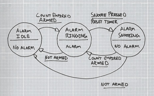
The alarm functions of the alarm clock.
Try mentally walking through the operation of the state machine. I see that I can't get from 'idle' to 'ringing' if the alarm clock is not armed. Also I can't get back to 'idle' by pressing the snooze button, I have to disarm the alarm. This meets my internal definition of how an alarm clock acts, so I proceed.
There isn't a way of actually tracking time yet, even if just for the experiment. Rather than keeping track of days, hours, etc. I want to only keep track of seconds. So I'll need to count seconds. Well, the LED toggling state machine does that already! I'll just change it to keep track and add the whole darn state machine in.
Re-using the blink state machine to count seconds.
As a benefit, I can block the blinking of the LED unless the alarm is going off, and use that as the debug output.
Here's the full source file (github): alarm_clock.ino
Hardware connections:
- Connect a normally open button between pin 7 and ground of an Arduino. This will serve as "SNOOZE."
- Connect a SPST switch between pin 9 and ground. This will serve as "ARM."
The code is very similar to the previous examples, but has two state machines built up in it.
First, the timer state machine states and variables:
//Timer FSM numbers
uint16_t msCounts = 0;
uint16_t sCounts = 0;

#define LED_OFF 0
#define LED_ON_WAIT 1
#define LED_ON 2
#define LED_OFF_WAIT 3
uint8_t timer_fsm_state = LED_OFF;
Next, the alarm state machine states and variables. The alarm time is set to 15 seconds from reboot (actually about 20 with error), and the snooze cycle is set for 5 seconds.
//Alarm FSM numbers
#define ALARM_SECONDS 15
#define SNOOZE_SECONDS 5
uint8_t alarmActive = 0;
uint16_t nextAlarmTime = 65535;

#define ALARM_IDLE 0
#define ALARM_RINGING 1
#define ALARM_SNOOZING 2
uint8_t alarm_fsm_state = ALARM_IDLE;
Loop() evaluates both state machines each time it runs.
//timer state machine
switch (timer_fsm_state)
{
  case LED_OFF:
    //Statements to execute every time LED_OFF is reached
    digitalWrite(13, LOW);
    timer_fsm_state = LED_ON_WAIT;
    break;
  case LED_ON_WAIT:
    //Statements to execute every time LED_OFF_WAIT is reached
    if(msCounts >= 1000)
    {
      timer_fsm_state = LED_ON;
      msCounts = 0;
    }
    break;
  case LED_ON:
    //Statements to execute every time LED_ON is reached
    if(alarmActive == 1)
    {
      digitalWrite(13, HIGH);
    }
    timer_fsm_state = LED_OFF_WAIT;
    break;
  case LED_OFF_WAIT:
    //Statements to execute every time LED_ON_WAIT is reached
    if(msCounts >= 1000)
    {
      timer_fsm_state = LED_OFF;
      msCounts = 0;
      if( sCounts < 0xFFFF )
      {
        sCounts++;
      }
    }
    break;
  default:
    break;
}

uint8_t buttonValue = digitalRead(7);
uint8_t switchValue = digitalRead(9);

//alarm state machine
switch (alarm_fsm_state)
{
  case ALARM_IDLE:
    if((sCounts >= nextAlarmTime)&&(switchValue == 0))
    {
      //Goto next state
      alarm_fsm_state = ALARM_RINGING;
      alarmActive = 1;
    }
    break;
  case ALARM_RINGING:
    if(buttonValue == 0)
    {
      nextAlarmTime = sCounts + SNOOZE_SECONDS;

      alarm_fsm_state = ALARM_SNOOZING;
      alarmActive = 0;
    }
    if(digitalRead(9) == 1)//If switch went off, goto idle instead
    {
      alarm_fsm_state = ALARM_IDLE;  // this overwrites the snooze button option
      alarmActive = 0;
    }
    break;
  case ALARM_SNOOZING:
    if(sCounts >= nextAlarmTime)
    {
      //Goto next state
      alarm_fsm_state = ALARM_RINGING;
      alarmActive = 1;
    }
    if(switchValue == 0)
    {
      //Goto alarm idle
      alarm_fsm_state = ALARM_IDLE;
    }
    break;
  default:
    break;
}
To operate, close the "ARM" switch and load the program.
Conclusion
In my experience, any coder who can diagram a program before writing it will succeed at the program. I've written one too many programs that ended up as a wad of nested 'if' statements because I didn't plan ahead. Inevitably, I needed to add one little thing that horribly broke the program and I was forced to re-evaluate my life choices. Using tools like state machine diagrams, flowcharts, class diagrams and unit tests have allowed me to write more complex yet maintainable code (while staying relatively sane). The state machine is just another idea to have in the toolbox and I hope that it will help you in the future!


I also come from a hardware background and when I began programming state machines the most difficult part was how to actually draw the state machines. However, once I figured out that the state transitions should be some sort or event (button press, timer tick, message received, etc) it made things a lot easier.After that I was constructing state machines using the good 'ol switch statement.
Then I came across this interesting post and my whole paradigm shifted forever. http://fabioutzig.com/2013/06/21/table-driven-state-machines.html Instead of constructing a state machine in switch statement I now write them in a table. It is so much easier to read, easier to edit, easier to debug. With more then just a few states the switch statement quickly gets out of control and unmanageable. With the 'table-driven' method everything is much cleaner. Sometimes a switch statement is just great especially where the processing is simple and needs to be very fast, but for more complex application level state machines the 'table-driven' method is king!
Table driven state machines are great but to get the most benefit from them you also need a state monitoring function for each state. You can already see the event function in the example shown in the link. It gets called when a particular event occurs for a given state. On the other hand the state monitoring function gets called repeatedly by the state machine "engine" when no events have occurred. In this function you might call a function that looks for "key presses" and generates an event when a key press is detected. This means that you only check for things within certain states. In some states you might want to check for key presses while in others you might want to check for key releases. This greatly simplifies code and reduces the monitoring overhead on the MCU. There is nothing to stop you sharing a state monitoring function between different states.
Nice link! Here's another one describing table-driven state machines:
Writing Efficient State Machines in C
Oh man, big switch statements...State machines are so much better in C++ with polymorphism. All the child state classes will define a Run method, which will return the next state, or itself. That way, each class only has to deal with the state changes it will change to next. It helps make complicated state machines easier to read, as you won't have a giant switch statement in the main loop, as it would look like this:
My C is really rusty, but I'm sure the pro's on here can make it work (function pointers in structs?)
I'm no object oriented pro but I've been coding exercises to get better. Recently I wrote a linked list of objects that is dynamically allocated to the heap (with no leaks! Yay!) Later, the thought dawned on my that the states could be connected in the way you describe, and I contemplated changing my 'snippet' implementation to be more object oriented. With 10 to 20 foreseeable states in a personal project, I weighed the benefit of flexibility vs. ease of implementation and came out thinking no, it's more important to get the thing working than to finesse.
I think the art of engineering is the decision of what solution to use for a particular problem. I was chatting with Byron in the office when the model-view-controller idea came up. There's an application where a switch statement most likely the wrong thing to use (unless maybe the controller had a subsystem implementing radio-like selects, for instance). Before that I was typing up how to implement a bit-banged synchronous serial interface for microcontrollers, and I couldn't come up with a decision on whether that should be switch statements or objects. I don't want to control low-level hardware from an included .cpp file, but I don't want a mess of my main() statement either. I think object orientation makes the machine tidy in code at the cost of hierarchical clutter, and it's the engineer's job to step in and proclaims "I think things!"
Having said that, you've got my curiosity piqued and so I have to do it now. Perhaps I'll come up with something I like better. Thanks for reading and making me think!
Hi MTaylor, I'm also a big fan of state machines and would really like to encourage people to use them where appropriate (which seems to be in a great many circumstances). I did however feel that your post was too detailed for the majority of amateur programmers and hobbyist makers and probably for the average professional programmer to see what the underlying benefits really are.
I would have lead with: In programming terms a state machine is a way of telling a program what to do when something happens and what to do until that thing happens. Because these things can happen at different times and in different orders trying to write pure code can often obscure the relationship between what can happen and when.
A greatly simplified way of describing the relationship is with the use of state diagrams. A quick look at a state diagram can quickly show where you have overlooked a relationship or where a relationship does not make sense. State diagrams are an incredibly powerful tool for solving even simple problems. And they are invaluable as a way of documenting code.
State machine diagrams come into their own when used in conjunction with CASE tools that convert the diagrams into executable code. Some of these tools even have a debug facility that allow a user to interactively trace the execution of code against the actual diagram used to create it.
This is a short document I prepared for some of my friends on the MIT PICLIST a few years ago.
http://www.xcprod.com/titan/state_machine_desc_033.pdf
Regards Sergio
The way I explain state machines is in terms of parsing HTML. If you need to parse something that's human written and has no formal definition of what order the tags will appear, the only way to parse it in software is with a state machine.
As each character is evaluated, we check to see what the next state should be. From there, you can implement logic which saves the data in each tag as it's processed and then later does something with the information collected. I wrote this one afternoon to solve a problem I was having and I keep going back to it to solve these kinds of problems. It runs relatively quickly even if it is a bit hard to follow due to the massive switch statements that you may wind up creating. In my opinion, you could also abstract this and write software which writes your switch statement for you based on a set of rules.
btw - this comment box is very code unfriendly :-( ….can't use the tab key….
I come from a hardware background so it's nice to see some high level state machine ideas. Thanks! Member #134773 brings up a good point so I looked it up lexical vs syntactic analysis and learned something. If we used your state machine to symbolize input, then built another state machine to make sense of they syntax of the symbols, we would be closer to something that can parse by the true definition.
But now I'm thinking, if the HTML is being rendered by something that changes and holds its own state (like an italics effect for instance), we don't care when the HTML triggers which effect, we're just chuncking through it while controlling some rendering engine (also a state machine).
State machines are everywhere. I love it!
Huh? (Just kidding). :-)
Thanks for your work on this. It is well-researched and plainly written. I'll be bookmarking it.
I'm interested in state machines as well, because I used to design machine control systems and write Programmable Logic Controller (PLC) ladder programs, which are essentially big complex Mealy state machines. One of the most successful prison control companies uses industrial PLCs to control the states of all the prison doors. It's the best and most secure way to insure that the state never arises where a prisoner can go where they should not be.
I think you're right in saying that most programs have state machines in them, whether intentional or not, and it's better to be intentional than haphazard. I'd like to suggest that every program with a menu or user-settable option has a state machine in it by definition, as are programs that use global memory as a method of signaling - such as signaling between interrupt routines.
Thanks for showing us how to think about them, diagram them, and use them.
Thanks for the comment!
I had never considered how a prison would be constructed before. I always assumed that there was some secret black box to controlling all the doors. Now that you point it out though, it's the perfect application for an industrial PLC (I used to design industrial control circuits). This is one where all the states and transitions would be fully specified and tested for all situations.
Signaling between systems (shared globals) is a good example too. Often I'll have a state machine that gets held up in some hold state until a flag has been modified by an associated ISR allowing the machine to progress. Similarly, building a TCP server and client application can be designed as state machines (to keep track of all the ACKS / handshaking flags). The difference is that the communicating systems are on separate pieces of hardware.