Enginursday Tapas
Rather than a lengthy exploration of a single subject, I'm going to touch on a couple of smaller dishes.

<floobydust>
The Teensy Plate
Working at SparkFun, it's hard to keep up with all of the cool technologies we have in the building. Sometimes interesting and useful things land in my lap when I'm not expecting them, and sometimes they coincide with me having the interest and time to dig deeper.
One of those opportunities found me last October. A friend was building a piece of interactive artwork and he needed need some troubleshooting help. He was going to put a Teensy 3.2 in it to play .wav files, but was having trouble getting the system integrated with a small power amplifier. I asked him to bring it to my office so we could get it working.
I'll admit I never worked much with any of the Teensy boards. I knew they were small, and Arduino compatible. In preparation for our debug session, I perused the schematics and chatted with a couple colleagues about their experiences with the Teensy.
As I gathered background information for troubleshooting, I got a closer look at the Teensy Audio environment -- I was pleasantly surprised by what I found! In a nutshell, it starts with a web-based user interface that is used to lay out audio processing blocks (and the menu of available blocks offers quite a few useful items). The web page exports code you paste into an Arduino sketch, then compile and load it into the Teensy. Paul Stoffregen, the guy behind the Teensy, has put a lot of work into this package, and development is ongoing.
I'm not going to get too deep into the basics of Teensy Audio here. If you want the crash course, you can start with this video.
I spent a fair amount of time through the winter getting familiar with the platform, and started planning how I'd like to build it into some more ambitious projects.
Stealth Feature
On January 16, Paul quietly announced that he'd added support for two simultaneous Audio Boards, allowing four channels of 16-bit input and output on a single Teensy.
To me this is a really useful feature -- one Teensy can be used where a pair were previously required. Coupled with polyphonic .wav file playback, you can play different files on each output -- or, in my case (I'm building a drum synthesizer), I'll be able to route each voice to its own analog output.
In the original thread, the finer details of getting everything connected and working were left as an exercise for the reader. I've got it working, and I'd like to share the magic recipe.
Parts
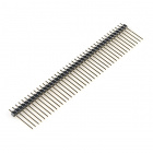
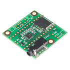
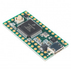
You'll need the following parts -- a Teensy 3.2, two Audio Adapter boards, and some male and female headers.

PCB rework
To use two Audio Adapters, you'll need to modify the boards to coexist.
First, you'll need to remove the 0.1 uF capacitor on Pin 15. That's ADC input A1 (or digital I/O 15), which will be repurposed as the TXD pin of the second audio channel.
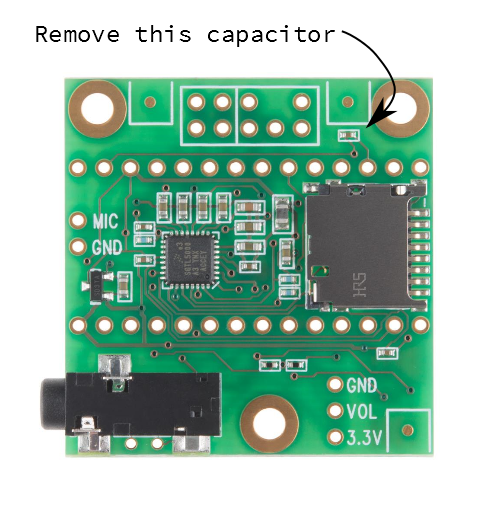
Remove this cap from both boards.
Then, you'll need to select one board to be channels 1 and 2, and the other to be channels 3 and 4. The 3 and 4 board needs some extra cuts and jumps.
The pairs of pads near pins 13 and 22 need to be cut apart. The trace between the center and left pads of the I2C address selector also need to be cut.
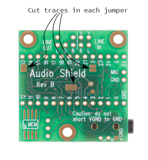
Cuts for channels 3 and 4.
Then, new connections need to be wired to those pads.
- The first two jumpers configure to codec to read and write alternate channels on the I2S peripheral.
- From the inner pad near pin 22, run a wire to pin 15.
- From the inner pad near pin 13, run a wire to pad 30 on the bottom of the Teensy.
- Use a solder blob to connect the center and left pads of the three-way jumper. This assigns the board to its secondary I2C address.
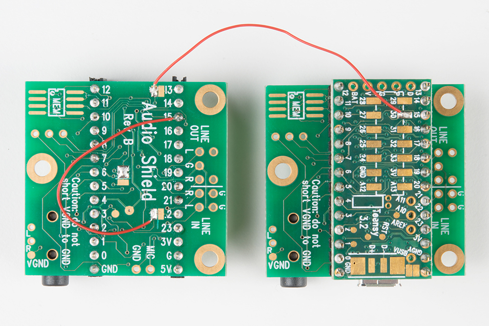
Connecting the channel 3 and 4 data lines.
Last, add the headers. For my stack, I put long pin headers on the bottom of the first Audio Adapter, then ran them through the Teensy and soldered them in place with the Teensy about halfway up the pins. This leaves the pads on the bottom of the Teensy accessible for future expansion. The other Audio Adapter got female headers on top of the board.
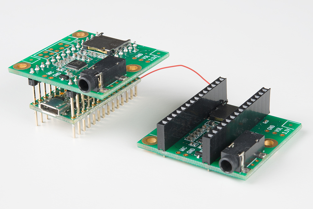
When you plug the boards into each other, make sure the orientation is correct -- the headphone connectors face the same way.
Software
To make use of the four inputs and outputs, you'll need to use the corresponding library objects. This four-channel wiring diagram simply passes the inputs to the outputs.
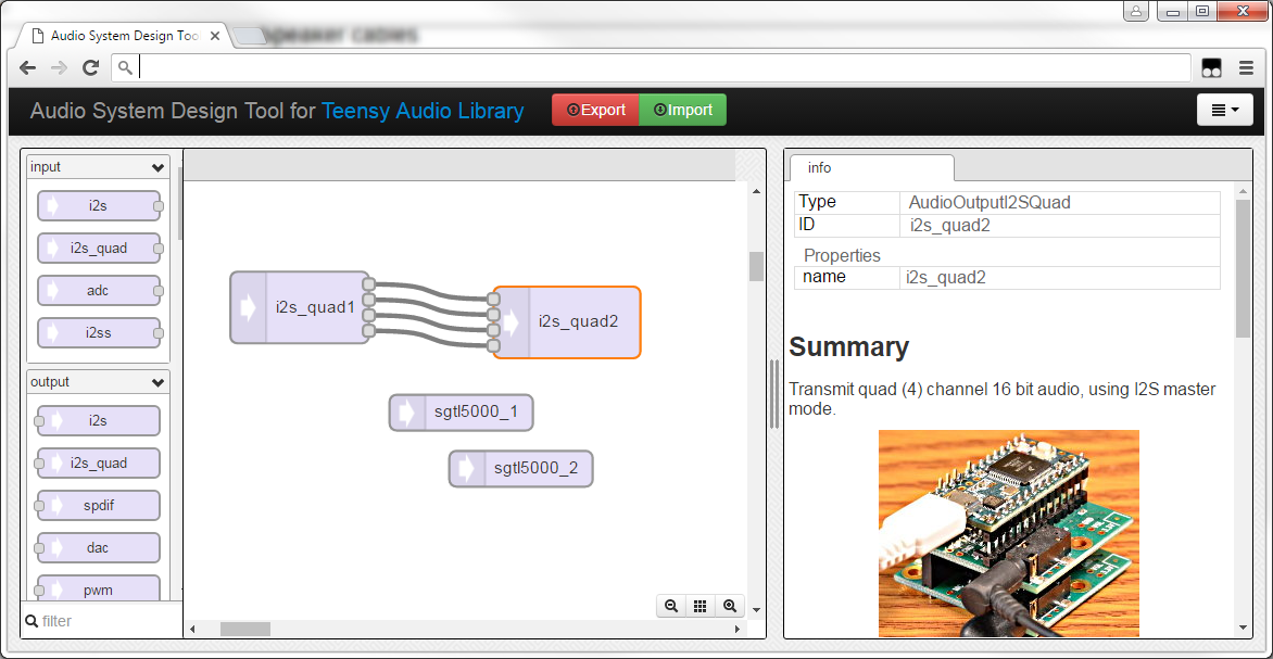
A simple four-channel patch.
Some details to note:
- The inputs and outputs are represented with
i2s_quadobjects, each providing four input and output terminals. - The two codecs are represented with individual control blocks,
sgtl5000_1andsgtl5000_2. - The codec objects need to have their I2C address assigned in
setup(), by callingsgtl5000_1.setAddress(LOW)andsgtl5000_2.setAddress(HIGH). - The quad-input object requires at least eight buffers. You might need to add a few extra when calling
AudioMemory()in yoursetup()function. - The potentiometers on the Audio Adapters no longer work, as pin A1 has been repurposed as a digital audio data pin for the second codec.
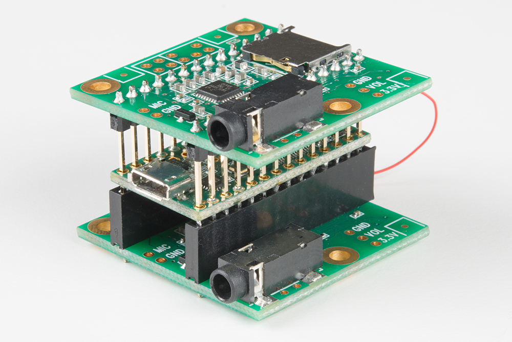
Finally, with two Audio Adapters, it's time to test four channel playback.

Four-channel audio test apparatus.
The Porridge Plate
Those of you who have been in the electrical engineering field for a while might remember when the late Bob Pease wrote a monthly column for Electronic Design magazine. I'm sure I'm not the only person who would grab each new issue, and immediately go hunting for Bob's Pease Porridge column.
Bob was a longtime staff scientist at National Semiconductor. He was an insightful engineer, and also an engaging writer and storyteller. As someone who has to do it regularly, I realize that writing about specialized engineering topics is hard. His columns made dry engineering concepts approachable, while sometimes diverging into subjects as varied as high-altitude hiking and defensive driving.
To commemorate the fifth anniversary of his passing, Electronic Design have released a new eBook with some of Bob's articles. If you're interested in analog subjects, downloading Focus On: Bob Pease on Analog, Vol I. is worth the free registration.
Since that's Volume I, I'm assuming there are more volumes in the works. In the meantime, there are many other articles in the Pease Porridge archive.
</floobydust>


Thanks for the "Heads Up" on Bob Pease! I really liked his articles and I grabbed the E-Book.
Hi, I am running into audio problems doing the 2 audio shield w. teensy 3.2 setup. I am using the standard test code example, included at the end of this post. I have removed the pin 15 capacitors on each shield I have done all the mods to the second shield described in the sparkfun tutorial (linked from the quad page): I get the message playing file 1 & playing file 2. The 1/2 channel card works fine. Nothing at all on the 3/4 channel card. There appears to be no data on pin 15. If I temporarily short the pin 22 pad to the pin 15 pad, I get channels 1/2 playing on the 3/4 shield, as you would expect. I built two different boards - each with the same problem. I also tried a modified board I had successfully used in the past - this also didn't work. I also tried setting pin 15 to output mode (not in the example). I've tried running at 96 Mhz and also 72 Mhz. Has something changed re. the support for the Teensy 3.2? I have tried several codes... I should also specify that we did the mods necessary to stack the two audio shields and that we do not have any shorts on the solders that I made ^^ Thanks to anyone who has some ideas!
So, I followed the guide and slightly adapted it to fit the Teensy 3.6, and it all seems to work.
Since I need some heavy delays, I soldered on a RAM on each audio board (my first on something that small, not easy), although in retrospect one chip might be enough. I haven't tried it yet, but just inspected the schematics, and now I can't figure out whether it would work, or (in worst case) fry the RAM chips, since they are on the same CS (pin 6).
Is this a problem? Any way to avoid it? (preferably without the need to unsolder the RAM chips).
Asked on the PJRC-forum, quickly got a response; https://forum.pjrc.com/threads/46781-Dual-Audio-Adaptor-Boards-with-23LC1024-RAM-chips
Short answer: Yes, it is a problem. It should be solvable though by cutting the connection to pin 6 on one of the boards, preferably such that the pull-up resistor is still connected to the CS pin on the memory chip, and then rewire it to be connected to a different pin on the teensy.
"Floobydust" is my new favorite word.
I know this is an older post, but hopefully someone sees my comment. I'm rather new at all this, so I need some assistance. The directions say to cut the trace between the left and center I2C pads, but the picture is pointing to the space between the right and center. Could someone please clarify that for me? Do I cut the left one, then basically reconnect the two pads with the solder blob? If so, why not just leave the trace connected to begin with?
Also, what's the best way to remove the capacitor in the first step? And do I remove it on both boards?
Thanks!
Several months after this tutorial was written, Teensy 3.6 was released. It run at about double the speed of Teensy 3.2 and have 4 times as much RAM. That extra capacity can be pretty useful for audio synthesis, especially if using 4 channels.
This mod works the same way, except the extra RX signal goes to pin 38 on Teensy 3.6, rather than pin 30 as documented for Teensy 3.2. This is documented in the Audio Library Design Tool right-side panel for the I2S Quad object.
https://www.pjrc.com/teensy/gui/?info=AudioInputI2SQuad
Confirmed, the arrow is correct. The TEXT IS INCORRECT. It should read "trace between the center and right pads of the I2C address selector also need to be cut".
While not easy to see in this low-res web image, when you look at the actual PCB with a magnifier to actually make this mod, you will see the trace is between the center and right side pad.
The 0.1uF capacitors on pin 15 will cause trouble for the extra data signal. If you connect audio shields together in the simplest, most straightforward way where all pins connect (similar the photos), both of their pin 15 pads connect together. Both capacitors need to be removed, since either would cause trouble.
If you were to cut the header, so there was no connection to pin 15 on the unmodified board, so that neither Teensy nor the modified board connects to it, then leaving the capacitor in place on the unmodified board would be fine. It can't interfere with the 2nd data signal if it's not connected between the boards. Obviously the capacitor must be removed from the modified board, so no matter how you connect between the 3 boards, you will need to do the capacitor removal on at least the audio shield where you cut the trace, soldered the alternate I2C address pads, and arranged for the data signals to do to other pins.
With an ordinary soldering iron, probably the simplest way would involve building up a small bead of solder on the tip of your iron. The part is so small that you can just lay a bead of solder on top to melt both sides at the same time. The part might stick to your iron's tip as you pull it away. If not, just a gentle press will easily push it aside from the pads, towards the large open area near the edge of the board. You can then pick it off with tweezers, if it doesn't fall off from the slightest touch.
A better way to stack the Teensy audio boards might be to make use of those long pin Arduion stackable connectors on the top board so you can just stack the two of them together, and then put the Teensy on top. In fact, that's how it's done on the Teensy web site.