
Some projects don't need to have a noble cause to better the world or make some aspect of daily life easier. Some projects are done just because you can, or it looks cool. Back in 2012, I worked on a group project for school with a simple task: Use a sensor and do something interesting. We decided to build a simple magnetic levitator to float a few magnets in midair, but there were parts of the project that I wasn't able to implement. The main feature I wanted to add was wireless power transfer.
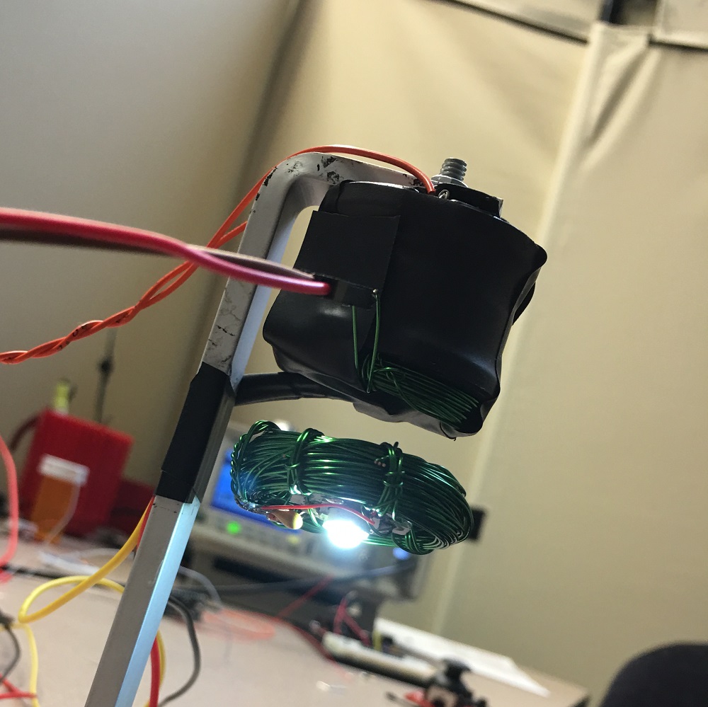
Wireless power works just like a normal transformer, except there isn't the iron core that's found in a traditional transformer. The physics, however, still work the same: current from the primary windings creates a magnetic field, which induces current on the secondary windings. The lack of ferrous material connecting the windings, though, means that the power transfer efficiency is significantly less. But let's see this thing in action!
Unfortunately, it's still not perfect. There's still too much oscillation at times, but I think that's because the comparator circuit output is only off or on (even though they're short pulses). Another reason could be from using a single sensor, which is picking up both the magnetic fields of the magnet and the inductor, resulting in a slight error. I'd also like to transfer more than just a watt of power to the LED, but without tighter and cleaner windings, I'm not sure how much more power I could transfer without adding too much weight.
If you'd like to build your own, check out the GitHub repository here. Have you ever worked on a project like this before? What kinds of projects have you worked on, just because you could? Let us know in the comments below.
Interested in learning more about LEDs?
See our LED page for everything you need to know to start using these components in your project.


what about some kind of Litz Wire? https://www.newenglandwire.com/en/product-selection-guide/litz-wire-and-formed-cables/litz-wire-theory
This wire is used when it is necessary to increase the amount of surface area without appreciably increasing the size of the conductor.
I've been working on something similar to this actually. Everyone knows about BB-8, right? Well, one of the big problems with reconstructions is that the head is heavy and almost always pretty dumb. Using magnetism and wireless power transfer, you can add a camera and some image processing to the head unit without adding a battery or lots of weight.
I've proved you can power a Raspberry Pi Zero (https://www.youtube.com/watch?v=A_yJUGsATo4) from a very basic wireless power module, and am currently working on making my own module to tailor the range to my actual robot. Coupled with a "floating head" I hope to have BB-8 run autonomously.
dear sir .. thanks for posting this great project. it seems so simple to build as well as complex. my questions are: what are the measurements of the main coil? is it necessary to make a metal or steel core such as the bolt? how about replacing the LED with a short strip of LEDs? thanks.
Check out the building tutorial here, which has a link for the inductor to levitate the magnets and the measurements for the wireless power coils. You might be able to use a short strip of LEDs, but they have to be the non-addressable ones. It would probably take a bit of testing to figure out the right current limiting resistor value on each LED in the strip, but it's theoretically possible.
Hi alex! Thanks for creating this project. Soon im going to create this project. But there are some questions for you. 1. why do we need a square wave signal? 2. In the end of article, you said that it's better to use a ne555 to generate a square wave signal to increase the efficiency. How do we connect the square wave signal? Thanks for your help
Please, check out Alex's follow up blog post. He has a tutorial for the project, linked there.
i already checked out the blog, but i got some question to discuss here. are the levitation circuit and the wireless power transfer different circuit? so do we need 2 mosfet for all circuit? or can we combine them into a circuit which only needs a mosfet? thank you
Hi there, in that case... it sounds like you are looking for technical assistance. Please use the link in the banner above, to get started with posting a topic in our forums. Our technical support team will do their best to assist you. Additionally, you can comment directly on the tutorial for more visibility regarding those instructions.
That being said, to answer your first set of questions:
As mentioned in the tutorial, under the Wireless Power section, in the Building the Primary Driver and Testing sub-section:
The square wave is for the wireless power transmission.
Under the same sub-section mentioned above, there is a circuit diagram and picture of how to attach the signal to the "transmitting" coil. (Tip: you are looking for the alligator clips.)
To answer your last set of questions: Yes, they need to be different circuits and the mosfets need to be separate. As mentioned under the Wireless Power section, in the Building the transmission coil sub-section:
For more information, there are plenty of resources on these topics online:
Hi!
I'm a high school student from Sweden who saw the video a few weeks ago and I'd like to reconstruct this for a physics project, and so I started looking around and found a parts list somewhere in the comments down below. I was wondering if I only need to buy one of each listed products (I know some of them are in packs, but I don't really know how many of each item that is needed?)
I also wonder if this is hard to do for someone who's not very familiar within the field. I only know the basics and a little bit above that.
Thank you in advance!
See the thread below.
Alex, My son, Owen thinks this is awesome! He would like to try to reproduce it. We have seen your schematic on GitHub. My son is 9 and not an electrical engineer so he needs a little help with a parts list. He has listed several of your parts from your video. Do you have a parts list posted anywhere?
Thanks!
Parts List:
(below are parts we don't sell)
Update: I totally forgot to link the hall effect sensor.
Thanks! That is a huge help!
Hi there, it sounds like you are looking for technical assistance. Please use the link in the banner above, to get started with posting a topic in our forums. Our technical support team will do their best to assist you.
That being said, here is a great tutorial on how to read schematics for your son to take a look at. I wouldn't focus too much on the detailed content at his age, it is pretty much all about identifying the symbols and part number or part value:
I'll try to ping Alex the Giant to see if he can link the products he used updated on the GitHub repository. Also, Alex was using a function generator... if you don't have access to one of those, this project will get really complicated or expensive.
Owen has the levitation circuitry and the power receiver circuit all wired up with the exception of a few questions: • What is the procedure for finding the resonant frequency? I have a function generator, how do I connect it to the circuit? How do I tell we’ve hit the resonant frequency? • The levitation circuitry diagram mentions putting the capacitor close to ic1, but I don’t understand where this would be? • What is the procedure for wiring the hooking up the power supply? Owen watched your video tutorial on "How to Power a Project". • What is the current at the 5V and 12V locations?
Thanks in advance for any help!
I made this a couple years ago, so my memory is a bit faded, but I just manually swept through the frequencies and kept an eye on the power supply's current draw. You'll know you're getting close to resonance as the current draw starts to increase, and as you pass resonance your current will decline.
The note about C1 being close to IC1 is just for best practice. The capacitor is to filter out any noise on the power supply. The longer the wire is between the decoupling capacitor and the IC you're trying to filter the noise from, there will be more parasitic inductance which can introduce noise back into the supply rail. If it's on a breadboard, you just want the capacitor closer to the op-amp than to the power input connections.
I'm not sure what you mean by procedure for connecting the power supply, but if you're using a single 12V supply, you can connect a 5V regulator to drop the voltage down from 12V to 5V to create the second power rail, or if using two power supplies, just connect 12V from one supply to the 12V rail, and 5V from the other supply to the 5V rail. With either solution, make sure you tie both grounds together.
The 5V rail uses very little current (probably a couple mA at most), the 12V supply needs to be pretty beefy. I think the supply I used was rated for 5A, but I levitator probably uses around 1A, and the wireless power transfer uses around 2A.
Owen here.
Alex thanks for all your help! There are some details that are not clear to me.
Regarding the resonant frequency:
b. What voltage do we set the function generator to?
Regarding the hall effect sensor in the levitation circuitry: 1. Where do I position the hall effect sensor?
I can come by today after 2:00 with my equipment and circuits if you or someone else at Sparkfun could help me with my final questions. Thanks! Owen
The red lead is the signal, the black lead is ground, which should be connected to the rest of your ground signals. The signal coming out of the function generator should be 5V peak-to-peak, with a 2.5V offset. So the high voltage should be 5V and the low signal should be at 0V. The function generator doesn't output very much current. the mosfet connected to the function generator is switching the current from the power supply on and off at the same rate as the frequency from the function generator. So the current you're monitoring is from the 12V power supply. Current measurement can be done by the power supply if it has the capability like this one or you can put a multimeter in series between the power supply and the circuit as shown in this guide.
All of the 12V power can be supplied by the same power supply, and all of the 5V power can be connected by the same 5V supply.
The hall effect sensor should be attached at the bottom of the levitation coil in the center so that it can detect the distance of the magnet from the coil. I used electrical tape to hold it place, with the flat side of the sensor facing the coil.
Hello Alex, Owen here, thanks for all the information. I have gone through the whole levitation circuit and fixed all errors I found. Next I then tried levitating the magnet, all it does is snap to the inductor. I have tried turning the potentiometer to change the location of the magnet, but it does not help and keeps snapping to the inductor. Any suggestions? Thanks for all your help with your awesome project!
I think the inductor might be wired backwards. The way the circuit works, is when the magnet is too far away, the op-amp's output should go high (12V) to allow current to flow through the inductor and generate a magnetic field to pull it up closer to the sensor. When it's gets too close, the op-amp's output should go low (0V) and let gravity pull it farther away from the sensor.
The first tip I would give is to disconnect the inductor from the circuit, and make sure the circuit is working correctly by measuring the output voltage of the op-amp with a multimeter. Without a magnet near the sensor, make sure the output voltage of the op-amp is reading close to 12V. If it's reading 0V, you should be able to adjust the potentiometer until it does. Next bring the magnet up to sensor and see if the op-amp's output voltage changes to 0V. If it doesn't change you might need to flip the magnet over so the other magnetic pole is facing the sensor, or adjust the potentiometer a bit more.
Once you see the output change, you'll want to adjust the potentiometer until the op-amp starts to switch between high and low when the magnet is around 2cm (3/4in) from the sensor. Once you have that dialed in make sure you keep track of which side of the magnet is facing the sensor. When you connect the inductor again, you should feel the magnet being attracted to the inductor and vibrate a little as you bring that top side of the levitation distance you set earlier. If it feels like the two magnetic field are repelling each other, or the side of the magnet that was facing the sensor during the testing wants to flip over to bottom, the inductor is most likely wired backwards. Once you swap the wires it should fix it.
Once you can feel it trying to levitate, that's when you've reached my point of frustration. It takes a bunch of patience to keep it in that sweet spot as you slowly let go and it levitates on it's own.
Hello Alex, Owen here. Thanks for the detailed description. Just to clarify after disconnecting the inductor I put the positive end of the multi meter in pin 6 of my op-amp and the ground in ground. I thought this was correct even though there is nothing in pin 6 from the schematic of an op-amp pin 6 is the output. With this set up it reads 0V and turning the potentiometer it still reads 0 or near 0 volts. Any suggestions?
Hey if you're still having trouble getting this working, I wanted to let you know that I finally had time to write a tutorial that walks through how to build it in more detail.
https://learn.sparkfun.com/tutorials/magnetic-levitation
If you're using an LM358 (pinout here), like used in the schematic, the input pins are 2 and 3 and the output pin is 1. so you should connect the positive end of the multimeter to pin 1 not 6. pin 6 is the inverting input of the second op-amp.
Thanks for the help I am having trouble to get the magnet to levitate i have the circuit right but it will either snap up to the electro magnet or fall down when i hold it to get it to levitate i feel it trying to levitate what do i do?
Hi Alex, I am currently building your circuits. I am able to make a magnet levitate (and the LED with the coil). I am also able to power the LED by induction. However, I am not able to make the LED levitate and light up at the same time. I was wondering if you had any ideas as to why I am not able to do both things simultaneously. Thank you!
It could be a handful of things, and without seeing the setup it's hard to say. It might be your power supply can handle the levitation or the wireless power transfer, but not both. It could also be that the hall effect sensor is being effected by the wireless power transfer transmitter.
One of the issues with my design is by having just a single hall effect sensor is the sensor detects the magnetic field of not just the magnets, but levitation inductor's as well. Shahriar over at The Signal Path, did and experiment a few years ago using two sensors: https://www.youtube.com/watch?v=LaGv2FHS5zg
Hope that helped a little. Good luck!
Thanks for the quick reply! I will definitely look into it. And I just have another question. When I was looking for the frequency of resonance, the current was lower while the LED had a brighter light. For example, at 40 KHz the current was stronger than at 200 KHz even though, at 200 KHz, the LED was giving a brighter light. Do you think the issue is my source or just my mesuring tools?
Hey there, I'm trying to recreate the set up you made and i was wondering what kind of wire you used for the inductor. Thanks!
The magnet wire I used had a diameter of 0.022", which should be 43AWG
Great! thanks :)
Awesome post. I'm a bit stuck on the levitation circuit though: What kind of power are you pulling running this?
I built this circuit part-for-part and I'm noticing that powering the FET drags the supply down considerably. The electromagnet has really low impedance at DC so this makes sense - I'm seeing my 12V supply drop to 0.09V at 3.12A when the FET is conducting. This also messes with the voltage on the rest of the circuit (since I'm driving an LM7805 to generate the 5V reference and it's source is dropping out).
Next attempt is to use two isolated supplies for the decision making portion of the levitation circuit and electromagnet driving portion. Any tips would be much appreciated!
The supply could be drawing too much current for a variety of reasons. The FET is controlled by the comparator circuit which compares the hall effect sensor's analog output voltage against the fixed voltage from the pot. Drawing too much current means that the voltage from the hall effect is too low, so more current is added to the inductor to try and pull the magnet closer to the sensor. To set the reference voltage from the pot, I would hold the magnet in my hand around half an inch from the sensor and with my other hand slowly increase the voltage from the pot until you feel the magnet start to lift from your hand.
The levitation current should only be around 1A. But the current draw is dependent on the mass of the object your trying to levitate. Obviously the heavier the object, the more energy (ie current) will be needed. Hope it helps!
Thanks for the reply Alex. My issues were primarily with the power supply. The DC resistance of the inductor and the on-resistance of the FET are really low. As a result, supplying 12V would result in some ridiculously high current. My supply was going down to 0.09V and 3.12A. The 12V was also powering the LM358, so when the voltage dropped it was no longer functioning properly. I isolated the problem by using separate power supplies for the FET/electromagnet and the rest of the circuit and that was able to fix the problem.
As a side note, I did notice that the resistance of the electromagnet significantly increases as it heats up. At that point the supply can push 12V 3A. The demand on the supply significantly reduces its slew rate so for anyone else with this problem I found it worked best adding a 4 Ohm power resistor in series with the electromagnet.
What is the part number for Q1 & Q2?
Any logic level N-Channel FET should work, but I used these.
I have actually had fairly good success pushing 5 watts plus wirelessly using a flyback inverter style circuit. I have a schematic of this in the instructions to kits that I sell. The instructions are available for free at the link on this page: https://bfieldlight.wordpress.com/2016/02/18/hobby-kits/ I don't know how the electromagnet circuit will react to the wireless power at this wattage, but since it is fairly stable and high frequency, so it may not influence the feedback circuit too much.
I might have to try that. I have a flyback transformer from a previous project
Nice, I'm ready to try to make one, but I have a few questions. On the diagram for the wireless power transfer it shows square wave input. Is that square wave input coming from pin 1 on the LM358? and does that mean that circuit replaces what was in the original levitation circuitry, or is it in addition to the original? Is D1 an IN4001? Is D2 an IN4733? And finally, I don't really understand the comment on the C1 capacitor that says to place near IC1. Does that mean nearly touching, or touching? What is that doing? Thanks
The square wave input was coming from my function generator. You could replace the function generator with a 555 timer and use a pot to sweep through frequencies though.
D1 is used to protect the source from high voltages created by the inductor. I used a 1N4007, but any rectifier diode will work. Same with D2, it's a half bridge rectifier so another 1N4007 should work, but I used a 1N4148 because it was smaller.
Anytime you use an IC it's good practice to have at least a 0.1uF cap near the supply pin to smooth out any ripple on the rail. I could have connected the cap directly to pin 4 and 8 of the LM358, but for aesthetic reasons I placed it nearby with the note.
Thanks, I understand it better now. I've got parts ordered and I'll google around for making a generator with a 555.
This definitely ranks way up there in the cool factor. Cleaned up and with professional packaging, this is something that I would expect to see in a science museum gift shop.
For those without a bench frequency generator, would you have any suggestions in regards to using either the Frequency Generator Kit - FG085 (KIT-11394) or SparkFun MiniGen - Pro Mini Signal Generator Shield (BOB-11420) to generate the square wave?
Even a 555 timer will work. You really just need a way to adjust the frequency to drive the gate of the FET. But the other products you've listed will work too.
I have tried the 555 method through a FET, which works great, and even better if you match resonant frequency well between your coil and a capacitor in parallel. Frequencies around 100 khz work well. The transistor used in this way does tend to heat up from being slammed on and off hard, which is why I switched to the flyback circuit, in which gates of the transistor are held just open enough to trigger on and off as a multivibrator at the coil capacitors resonant frequency.(see link to kit instructions as I posted above) This even does a good job of matching mutual inductance of your transmitter receiver pair. It does tend to work as an induction heater if you have a tight coil though or high permeability core or close proximity unloaded resonant receive coil.
Awesome! I'm glad you were able to get it to work. That's something I should have mentioned in the video. Both primary and secondary should be tuned properly for maximum power transfer. The FET shouldn't be over heating when the gate is saturated though, because Rds should be in the milliohm range. A mosfet driver should help with thermal issues.